VOGONS


First post, by assasincz

User metadata
Rank Member
Rank
Member

Hi guys

I hope you all are doing well in these peculiar times...

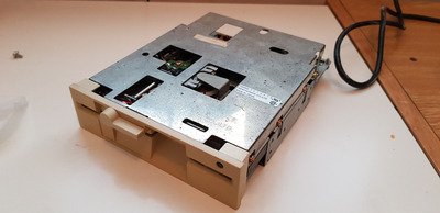
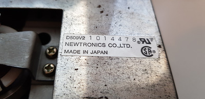
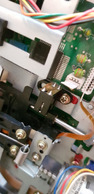
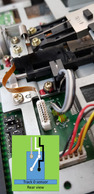
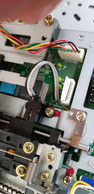
So I just acquired a box of free old PC stuff and in it, there is this lovely Mitsumi D509V2 drive that will go nicely into 286 project I am currently working on.

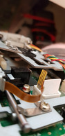
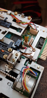
Cleaning it, I notice just one broken thing, a ribbon cable that presumably leads from the control PCB to the optical switch of the head is broken. I reckon I can fix it and make new leads, but can any of you help me figure out the pinout, which of the four leads go where? I cant find any schematics....Thanks

20200415_070133.jpg
Filename
20200415_070133.jpg
File size
950.71 KiB
Views
1198 views
File license
Fair use/fair dealing exception
20200415_070138.jpg
Filename
20200415_070138.jpg
File size
1.2 MiB
Views
1198 views
File license
Fair use/fair dealing exception
20200415_065908.jpg
Filename
20200415_065908.jpg
File size
993.18 KiB
Views
1198 views
File license
Fair use/fair dealing exception
20200415_065851.jpg
Filename
20200415_065851.jpg
File size
1.49 MiB
Views
1198 views
File license
Fair use/fair dealing exception
20200415_065858.jpg
Filename
20200415_065858.jpg
File size
1.05 MiB
Views
1198 views
File license
Fair use/fair dealing exception

Reply 1 of 7, by maxtherabbit

User metadata
Rank l33t
Rank
l33t

That's the track 0 switch. One pin pair is for an LED, the other is a phototransistor. Top 2 pins and bottom 2 pins are paired, usually the LED is on top. DONT remove the switch, it requires precise alignment

Reply 2 of 7, by assasincz

User metadata
Rank Member
Rank
Member
maxtherabbit wrote on 2020-04-15, 12:42:

That's the track 0 switch. One pin pair is for an LED, the other is a phototransistor. Top 2 pins and bottom 2 pins are paired, usually the LED is on top. DONT remove the switch, it requires precise alignment

Hi

Thank you. So this identifies the sensor pinout, but I also need to know to which leads of the broken-off flat cable right next to it should be connected, do you know? I just noticed that the flat cable has only three leads, maybe one is common ground?

Well eventually I think I will go hit-and-miss approach to see if any combination works, I cannot really make it any worse....

Reply 4 of 7, by assasincz

User metadata
Rank Member
Rank
Member
maxtherabbit wrote on 2020-04-15, 20:44:

I have no idea. Try to find the service manual for that model drive online. If anything the common is probably the +5.

Hi,

Well it occured to me that I can try and find any picture of this particular drive model and check if I can see the cabling and which lead goes where from it. So I actually found this article and figured it out. I add simple diagram to one of the photos

So I removed the flat cable connector from the main PCB, soldered in some wiring directly to the trough-pins, and this is my result

02.jpg
Filename
02.jpg
File size
310.66 KiB
Views
1120 views
File license
Fair use/fair dealing exception
01.jpg
Filename
01.jpg
File size
1.12 MiB
Views
1120 views
File license
Fair use/fair dealing exception

It appears to be a success, the drive now resets to Track 0 and seeks on PC startup. Seems to work normally.
I just now have to get some 5.25" floppy disk to try if it actually reads and writes, and I do not have any

Reply 6 of 7, by assasincz

User metadata
Rank Member
Rank
Member
maxtherabbit wrote on 2020-04-17, 15:00:

nice clean soldering job. you didn't unscrew the sensor did you?

I did, unfortunately. It was impossible to get to it. You can see from the picture that the sensor is held in place by a screw, and a blob of paint/adhesive was added to maybe secure it in place (?).
In the picture, you can see the crack in the pain, some of the blob came off the metal with the sensor. I reckon I got it back in same position with maybe ±0,1 mm tolerance, how accurate does it need to be anyways....

Well we will definately see what happens once I get my hands on some disks...