First post, by n0m4d
Rank
Newbie
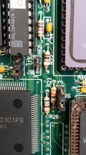
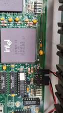
Hi. Any idea how to connect this panel to this motherboard?
Turbo switch has 3 pins, j8 just 2 its a turbo button connector.
Hi. Any idea how to connect this panel to this motherboard?
Turbo switch has 3 pins, j8 just 2 its a turbo button connector.
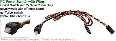
Of the three wires coming from the display/turbo button only two are actually necessary/used. The middle of the three wires is tpyically ground so you can try the middle wire plus one of the two outer wires to get it working.
The three wires are meant to offer the opportunity to reverse the way how the turbo button works, either pushed in or pushed out for turbo action.
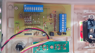
Actually, it's more complicated. The wires from the turbo button must first go to the pcb above. From there, they go to the mainboard. Probably the 4-pin header is for the switch and LED and the 2-pin header goes back to the mainboard. But that's just a guess.
The original setup of this 'system' has 2x3 wires coming from the turbo button.
1x3 wires go to motherboard and 1x3 wires go to display and the button thus serves both motherboard and display simultaneously.
PS However, in this case I assume that the display should be connected to the turbo led header on the motherboard.
PARKE wrote on 2020-04-26, 12:59:The original setup of this 'system' has 2x3 wires coming from the turbo button.
I know these switches with 2x3 pins, I have a bag full of them. However, I don't see what "original setup" is supposed to mean here. The front panel of the system posted by n0m4d uses a different (and more common) variant and I don't think that was ever different.
What I meant is that a fair number of the oldest turbo displays that are documented at http://www.minuszerodegrees.net/led_speed_dis … eed_display.htm
have a 3-pin connection that is controlled by the turbo switch and I used the term 'original' for it. The display in this thread seems to differ but that does not change the way how the 3 wires from the turbo button are supposed to be connected to the motherboard imo.
