First post, by Predator99
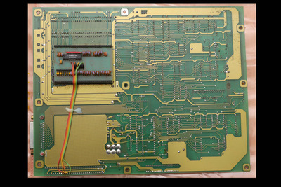
No questions here at the moment. I will post how I try to get my Commodore PC-10 XT split-board(s) running, PCB-ASSY 380000-01. I got it within this lot...:
Bought these (retro) hardware today
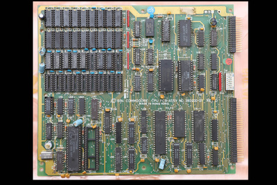
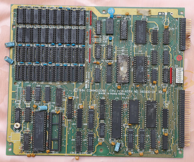
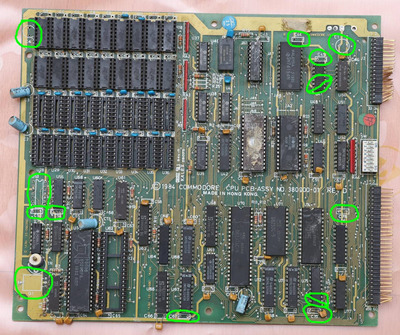
CPU board:
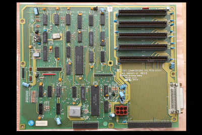
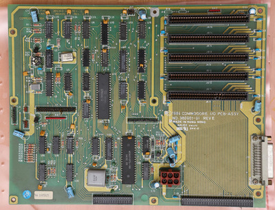
ISA/PSU board:
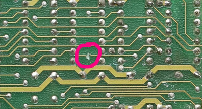
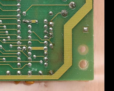
Somebody did some soldering practice on the CPU-board and some parts are missing. The 2nd RAM-bank also looks like a bad diy work but will care about this at the end.
The ISA/PSU board looks OK and complete.
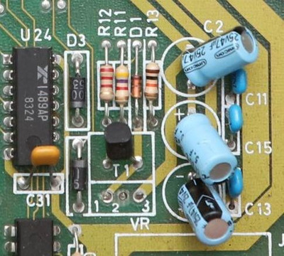
Missing parts in green circles:
I have found some photos of the complete boards here:
https://oldcomputer.info/gallery.php?spgmGal= … =20#spgmPicture
Technical refrence is here, parts list on p83:
http://dostalgie.de/downloads/pc10-20-10II-20 … ODORE_EN_DE.pdf
So I need:
Q1: OSC 14.318 MHz
C1 / C4: Electr. cap 25V or 16V / 47µF
C44 / C45 / C53 / C54 / C67 / C70 / C75: Radial ceramic cap 104 (0.1 µ / 50 V)
U53: DM74LS02N
Cap U47: (A9) 330pF cap between Pin 7 and Pin 10 of U47 (p60)
Cap U75: not required?
Hope I have all parts in spare.