VOGONS


Reply 20 of 59, by Predator99

User metadata
Rank l33t
Rank
l33t

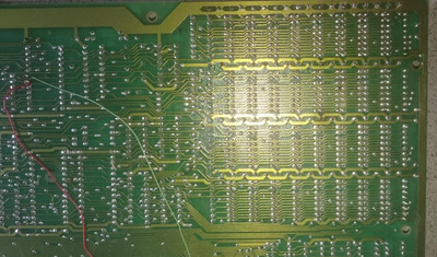
Made some progress. The patch wire didnt change anything.

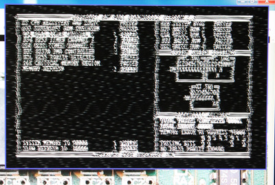
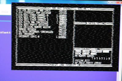
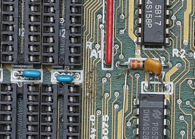
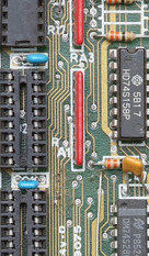
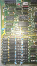
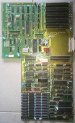
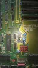
But I tried to insert a RAM in the top row and I noticed something changed. And indeed, after populating the full bank it passes the "16 K critical memory region" test! In the reference picture this bank is soldered with RAMs too...only noticed the empty 2nd bank:
https://oldcomputer.info/pictures/gal/Museum/ … re_PC10/025.jpg

But next error: "Memory refresh" fails....

IMG_0974r.jpg
Filename
IMG_0974r.jpg
File size
990.68 KiB
Views
707 views
File license
Fair use/fair dealing exception

Reply 21 of 59, by Predator99

User metadata
Rank l33t
Rank
l33t

...and even more progress. Replaced all RAMs with a single kind of 4164s...now it also passes the refresh test 😀 RAM is OK 😀

Now I tried to switch to the orginal ROM but nothing.

Attachments

  • IMG_0975r.jpg
    Filename
    IMG_0975r.jpg
    File size
    684.58 KiB
    Views
    706 views
    File license
    Fair use/fair dealing exception

Reply 24 of 59, by MJay99

User metadata
Rank Member
Rank
Member

Personally, I would try adding all those, including C44, C45, etc... Maybe this causes side effects on the graphics card and in some ICs...

Edit reason: wrong interpretation of filter caps.

Last edited by MJay99 on 2020-05-04, 21:38. Edited 2 times in total.

Reply 26 of 59, by MJay99

User metadata
Rank Member
Rank
Member

Also just had a look at the schematics, the mentioned failed timer is U71, which is the one right near the probably formerly shorted capacitor.
U70 is down the chain from it, and seems to have gotten quite a hit (there seems to be a dent in it) - maybe the issue stems from that area...?

Reply 27 of 59, by Predator99

User metadata
Rank l33t
Rank
l33t

I am not an expert, but as far as i understood all these "small" caps are filter caps and not really required for operation? Of course I plan to add them later but currently I dont have enough in spare.

I think there is just dirt beneath the RAMs, better photo attached but I will verify tomorrow.

Supersoft RAM test is OK, therefore we should focus on the other parts (DMA, Timer, Interrupt)?

But U70 looks OK to me?

Attachments

  • IMG_9031r1b.jpg
    Filename
    IMG_9031r1b.jpg
    File size
    77.71 KiB
    Views
    696 views
    File license
    Fair use/fair dealing exception
  • IMG_9031r2.jpg
    Filename
    IMG_9031r2.jpg
    File size
    137.75 KiB
    Views
    697 views
    File license
    Fair use/fair dealing exception

Reply 28 of 59, by MJay99

User metadata
Rank Member
Rank
Member
Predator99 wrote on 2020-05-04, 21:06:

I am not an expert, but as far as i understood all these "small" caps are filter caps and not really required for operation? Of course I plan to add them later but currently I dont have enough in spare.

You're right, of course (and I am definitely not an expert either). My idea was mostly, that with so many missing, it maybe could be related to the issues you're seeing in the graphics - but it's a very wild guess, of course.

It's also hard to tell from the picture, but to me it did look like U70 had gotten a hit. So, I guess, it's just a scratch?

Reply 29 of 59, by pentiumspeed

User metadata
Rank l33t
Rank
l33t

TTL and dram memory makes noise on the supply rails during high to low and low to high transients. You will need to replace all the missing bypass capacitors as minimum. The 2 layer boards are much harder to keep quiet as not enough bulk in power and ground rails.

Cheers,

Great Northern aka Canada.

Reply 30 of 59, by pentiumspeed

User metadata
Rank l33t
Rank
l33t
pentiumspeed wrote on 2020-05-04, 22:19:

TTL and dram memory makes noise on the supply rails during high to low and low to high transients. You will need to replace all the missing bypass capacitors as minimum. The 2 layer boards are much harder to keep quiet as not enough bulk in power and ground rails. Also you will need to replace the larger electrolytic capacitors and replace missing ones as well, 100uF 16V low ESR will do wonders.

Inspect all the sockets really carefully, these sockets used in this board you have is low quality type. I had to fix bent contact in one socket for the zenith 8088 PC 30 years ago, that was exact type of sockets.

Cheers,

Great Northern aka Canada.

Reply 31 of 59, by Predator99

User metadata
Rank l33t
Rank
l33t

I dont like these sockets, too. Think replacing them would be too much effort. As written, RAM seems to work now.

I have ordered all missing components including the voltage regulator and will report. But I would be surprsised if this solves the remaining problems...

Reply 32 of 59, by Predator99

User metadata
Rank l33t
Rank
l33t

Short update here:
I installed
- 330pF cap between Pin 7 and Pin 10 of U47 (p60)
- LM7905 regulator

Now all the voltages on the post card are there, but no change in Supersoft output.

No time to install the bypass capacitors so far...will do this next.

Reply 33 of 59, by pentiumspeed

User metadata
Rank l33t
Rank
l33t

Yes, please install all the bypass capacitors. The dumb 2 layer is very hard to design around to keep power planes quiet, hence bypass capacitors is required, one 330pF cap will not be enough.
Also check all large ICs does have all the VCC input pins are checked for voltage and bypassed properly.

TTL, LSI and memory data sheets *requires* bypassing right next to the *each* VCC pin (fat and very short track). and to strong ground plane. This was mandated back in the day in early days of TTL and transistor based logic when they worked with 2 layers boards before 4 layers and more became common. Even now with 4 layers or more boards, still a good practice to bypass to any VCC pins and still is.

Cheers,

Great Northern aka Canada.

Reply 34 of 59, by Predator99

User metadata
Rank l33t
Rank
l33t

OK, I think now I added all missing components (bad solder work - no time, bad camera - battery for EOS empty...).

No change at all.

Will test the VCCs next...

Thanks again!

Attachments

  • DSC_0001r.jpg
    Filename
    DSC_0001r.jpg
    File size
    700.68 KiB
    Views
    625 views
    File license
    Fair use/fair dealing exception
  • DSC_0003r.jpg
    Filename
    DSC_0003r.jpg
    File size
    725.74 KiB
    Views
    625 views
    File license
    Fair use/fair dealing exception
  • DSC_0004r.jpg
    Filename
    DSC_0004r.jpg
    File size
    961.2 KiB
    Views
    625 views
    File license
    Fair use/fair dealing exception
  • DSC_0002r.jpg
    Filename
    DSC_0002r.jpg
    File size
    624.17 KiB
    Views
    625 views
    File license
    Fair use/fair dealing exception

Reply 35 of 59, by Predator99

User metadata
Rank l33t
Rank
l33t

I checked all ICs and all have their 5V supply.

One thing I noticed: The CLK on the 8088 as well as on the ISA bus is only 3.5 MHz (instead of 4.7?). Thats also the output of the 8284. On the input pins of the 8284 my Multimeter only shows 87 kHz - but there should be 14.3 MHz from the crystal? I assume that trimmer is of the wrong type....
Maybe this can also explain the bad display on the CGA. Also the output from the speaker is very silent and slow...

Reply 36 of 59, by matze79

User metadata
Rank l33t
Rank
l33t
Predator99 wrote on 2020-05-04, 21:06:

I am not an expert, but as far as i understood all these "small" caps are filter caps and not really required for operation? Of course I plan to add them later but currently I dont have enough in spare.

Sometimes such a missing Cap can cause a lot of problems, it should not be Underestimated.

https://www.retrokits.de - blog, retro projects, hdd clicker, diy soundcards etc
https://www.retroianer.de - german retro computer board

Reply 37 of 59, by Predator99

User metadata
Rank l33t
Rank
l33t

I already installed all missing caps.

So I removed the trimmer and measured the 14.3 MHz crystal - shows again only 87 kHz.

For the other crystal I get 1.8 MHz as specified.

My Multimeter is specified for up to 20 MHz. So I assume that (new) crystal is not working...

Reply 38 of 59, by MJay99

User metadata
Rank Member
Rank
Member
Predator99 wrote on 2020-05-18, 19:19:

One thing I noticed: The CLK on the 8088 as well as on the ISA bus is only 3.5 MHz (instead of 4.7?). Thats also the output of the 8284. On the input pins of the 8284 my Multimeter only shows 87 kHz - but there should be 14.3 MHz from the crystal? I assume that trimmer is of the wrong type....
Maybe this can also explain the bad display on the CGA. Also the output from the speaker is very silent and slow...

A lower clock does explain a lower pitch and slower beeper - I have gone the opposite way and just put a faster crytal in. That sped up the beeper and also an attached Soundblaster 1 (since it seems to derive timing from the MB - actually that's still an open project on my side to fix that, i.e. separating CPU clock from the rest of the system). I didn't test CGA back then, but can at least say that VGA had no problem with that faster clock. But a long time ago, I also think I read about CGA being dependend on the system clock... someone correct me if I am wrong. So, certainly I would also try to get it back to where it's supposed to be 😀

Reply 39 of 59, by Predator99

User metadata
Rank l33t
Rank
l33t

Yes but I think with a faster one the 8088 will not keep up...maybe I will try a 20MHz to see what changes.

Already installed a spare 14.3 MHz (from the same lot than the other one) - no change.

Have to think about that before I continue...

And yes, I am also almost sure the CGA depends on the mainboard clock.