Reply 40 of 59, by Predator99
Rank
l33t
Hmm..OK couldnt wait and installed a 20 MHz crystal: Now it shows 86 kHz on the crystal and 4.4 MHz on the 8088
Doesnt make any sense to me.
Enough for today...
Hmm..OK couldnt wait and installed a 20 MHz crystal: Now it shows 86 kHz on the crystal and 4.4 MHz on the 8088
Doesnt make any sense to me.
Enough for today...
Good idea to replace all the crystals. 14.818MHz is master clock for XT. This is also color burst frequency as well for the video output.
Cheers,
Great Northern aka Canada.
Predator99 wrote on 2020-05-18, 20:11:Hmm..OK couldnt wait and installed a 20 MHz crystal: Now it shows 86 kHz on the crystal and 4.4 MHz on the 8088
Just out of curiosity: Did you maybe see any change in the graphics output at 4.4 MHz?
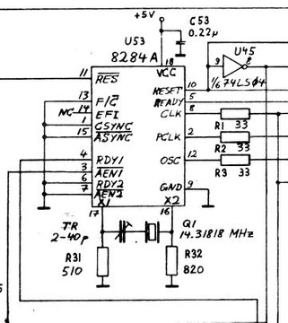
The circuitry around the crystal seems rather simple: Just two resistors (R31 at 510R / R32 at 820, plus the trimmer). If those two resistors check out (and the trimmer isn't broken), the only other element would be the U53 / 8284A...
But since I am fully out of my depth with them, maybe I can pick the brains of a colleague of mine who is an actual electrical engineer about oscillator circuits and such a failure mode...
Good place to start for sure, that's clock generator and timings IC.
Cheers,
Great Northern aka Canada.
Yes, I think there is a good chance that this clock issue is the source of the remaining problems.
That circuit is well described at minuszerodegrees:
http://www.minuszerodegrees.net/5150/misc/515 … ch_settings.htm
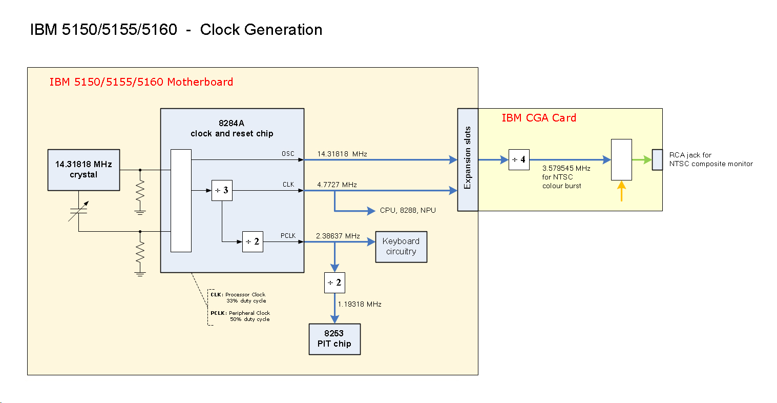
http://www.minuszerodegrees.net/5150_5160/mis … _generation.jpg
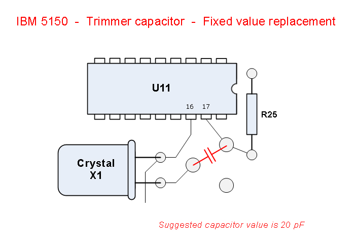
http://www.minuszerodegrees.net/5150/motherbo … replacement.jpg
What is really strange to me: When removing that trimmer and turning on without it the frequency measured directly at the crystal is still only 86 kHz instead of 14.3 18MHz. Its the same with the both 14.318 crystals I tested and similar with the 20 MHz.
So its not the 8284A. I will take a closer look at those resistors...but it should be very unlikely that they fail...
Predator99 wrote on 2020-05-19, 08:41:What is really strange to me: When removing that trimmer and turning on without it the frequency measured directly at the crystal is still only 86 kHz instead of 14.3 18MHz. Its the same with the both 14.318 crystals I tested and similar with the 20 MHz.
Don't trust multimeter readings. These things are only good for strong signals (and sometimes only calibrated for square wave). Also you are loading the crystal a lot by trying to measure it directly, it might just be switching to some weird n-th harmonic because of that. That you get a lousy 87-something kHz on the crystal but multiple MHz on the amplified output is a proof of that.
What you need is an oscilloscope, and preferably 10:1 probes rated at 100+ MHz so that you can actually see what is going on without distorting anything. This is especially important for the CPU clock as, if memory serves, it's not a 50% duty cycle but something like 33%. That has to be checked too.
Deunan wrote on 2020-05-19, 09:32:Don't trust multimeter readings. These things are only good for strong signals (and sometimes only calibrated for square wave).
[...]
What you need is an oscilloscope, and preferably 10:1 probes rated at 100+ MHz so that you can actually see what is going on without distorting anything.
I actually got the same information from my colleague, he also expects multimeters to not work on the oscillator circuit and recommended either a frequency counter / meter or oscilloscope.
Hi Deunan, yes I agree to that.
But I think the value I read on the CPU and on the ISA-bus is correct. I tested this with the same Multimeter on many other Mainboards and I got correct values...
So I assume there is indeed a problem with the clock on this board. See also the bad CGA output and the silent/slow output on the speaker during Supersoft-testing...
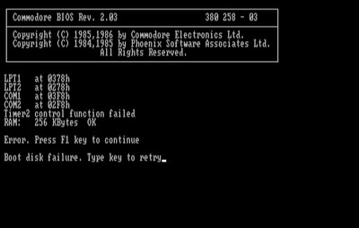
Made some progress. On the inputs of the 8253 I measured exactly the 1.19 MHz it should have - therefore the 14.318 MHz crystal and the clock generator seem to be OK.
However, according to the Supersoft Manual
http://www.minuszerodegrees.net/supersoft_lan … rs%20Manual.pdf
all the failed tests...
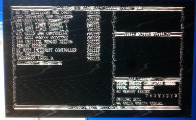
- 8253 timer channel 0/1/2
- 8237 DMA controller
- Interrupt level 0
...are related to the 8253. Therefore I desoldered it and tested a spare one.
Result: No change in the Supersoft test results...but the now there is a loud and very clear output from the speaker in the correct speed. So it was no wasted time...
..and no surpise: Without the 8253 installed I get exactly the same error pattern and again that silent clicking sound from the speaker.
So it seems to be totally clear that the problem has to be related to a circuit around the 8253...
So summarized I have the following status:
Supersoft fails the tests:
- 8253 timer channel 0/1/2
- 8237 DMA controller
- Interrupt level 0
RAM/parity/refresh is OK
8259 Interrupt Controller is OK
Hot interrupt is OK
In addition, output from the speaker is very silent/slow.
Because of this error pattern I desoldered the 8253 and put it on a socket. With a replacement 8253, I see the same Supersoft error pattern, but the output from the speaker gets loud and clear.
When completely removing the 8253, error pattern stays also the same, but I get again the silent/slow output from the speaker...
That means: The original 8253 was indeed defective, but the replacement didnt solve all problems.
- channel 0 (IRQ) is defective all the time
- channel 1 (DRAM refresh) does not seem to be required to pass the Supersoft-test
- channel 2 (speaker) only works with the replacement 8253 installed
So...what is the reason for this behaviour..? 😀
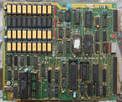
Check all the data lines that go to the 8253 chip, possibly something is not getting through and so it doesn't work as it should. Chances are the old chip is actually good but the line that's broken is floating at different level and causing a different behaviour. If the traces check out OK then it could be one of the '245 bus drivers that went bad.
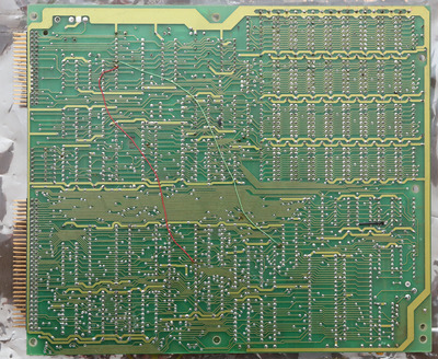
There seems to be one clipped line next to the 8253, plus a couple of spots that could also be nicks (or just dirt):
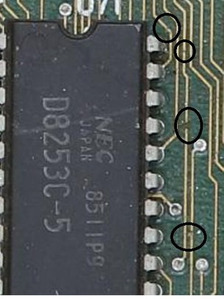
Maybe worth having a look there?
I had once a hard drive that would not work, searched the board for broken traces and found one, very tiny. Fixed that.
I suggest you do that?
Cheers,
Great Northern aka Canada.
Very good eyes - I will check this, thank you! But I assume its only dirt.
In the mean time I decided to desolder the U73 and U75. This was not as easy as for the 8253 and I destroyed both ICs and damaged a via in this process.
Thats the result when you do something when you are in a hurry (which is unfortunately almost always the case for me...)..! 🙁
For the 74LS273 I didnt have a replacement so I have to wait for the spare to arrive...
I checked all traces to the 8253 - all OK.
I replaced U73 (74LS245) and U75 (74LS273) with new ones - no change.
Think without a more systematic approach to this I will have no success. I will put this board aside and continue with it later...
It works...!
As a last try I started piggybacking all ICs I have in spare. One of the last one was the 8237 DMA controller...with a new one on its back it runs..! Should have started with that right at the beginning...
Supersoft:
Turbo XT BIOS
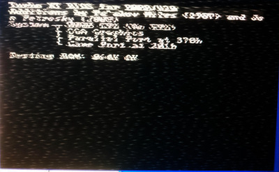
...and with VGA
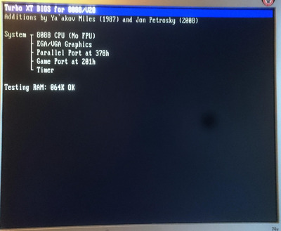
Still silent with the original BIOS but this should be easy. First I need to replace that 8237...
Well, that is awesome news! Great to see it back alive! 😀
awesome, good job :3
Thanks again for your ideas and your support!! 😀
So this is the current status of the CPU board.
Still some minor problems:
- POST still hangs sometimes. Didnt notice this with the piggybacked 8237 yesterday, so maybe bad soldering.
- only 64k RAM detected. The black ones are known working. If I put them in the top bank its still only 64k. I am not sure if this board expects 4164 or 41256 however. DIP switch seems to be "3,4 - 00 - 640kB of RAM installed, 10 - 512kB of RAM installed, 01 - 256kB of RAM installed, 11 - 128kB of RAM installed" - so there is not option for 64k only
- Original BIOS still silent. I am sure the ROM is OK, it works in PCem.
EDIT: Manual says it must be 256k or 128k DRAM, therefore 4164 will not work and there is no use for my gold-RAMs in this board 😉
