VOGONS


First post, by filipetolhuizen

User metadata
Rank Oldbie
Rank
Oldbie

Hello,
On the back of my CP-300 (TRS-80 Model III compatible) there is a 3-Pin DIN Video connector which looks like this:
Dc300.jpg
Some Monitors at the time used this plug, but the CP-300 was mainly hooked to TVs the same way early consoles used to be (there's a TV output jack as well, which is RCA, but not meant for composite video) so there's lots of image and sound noise.
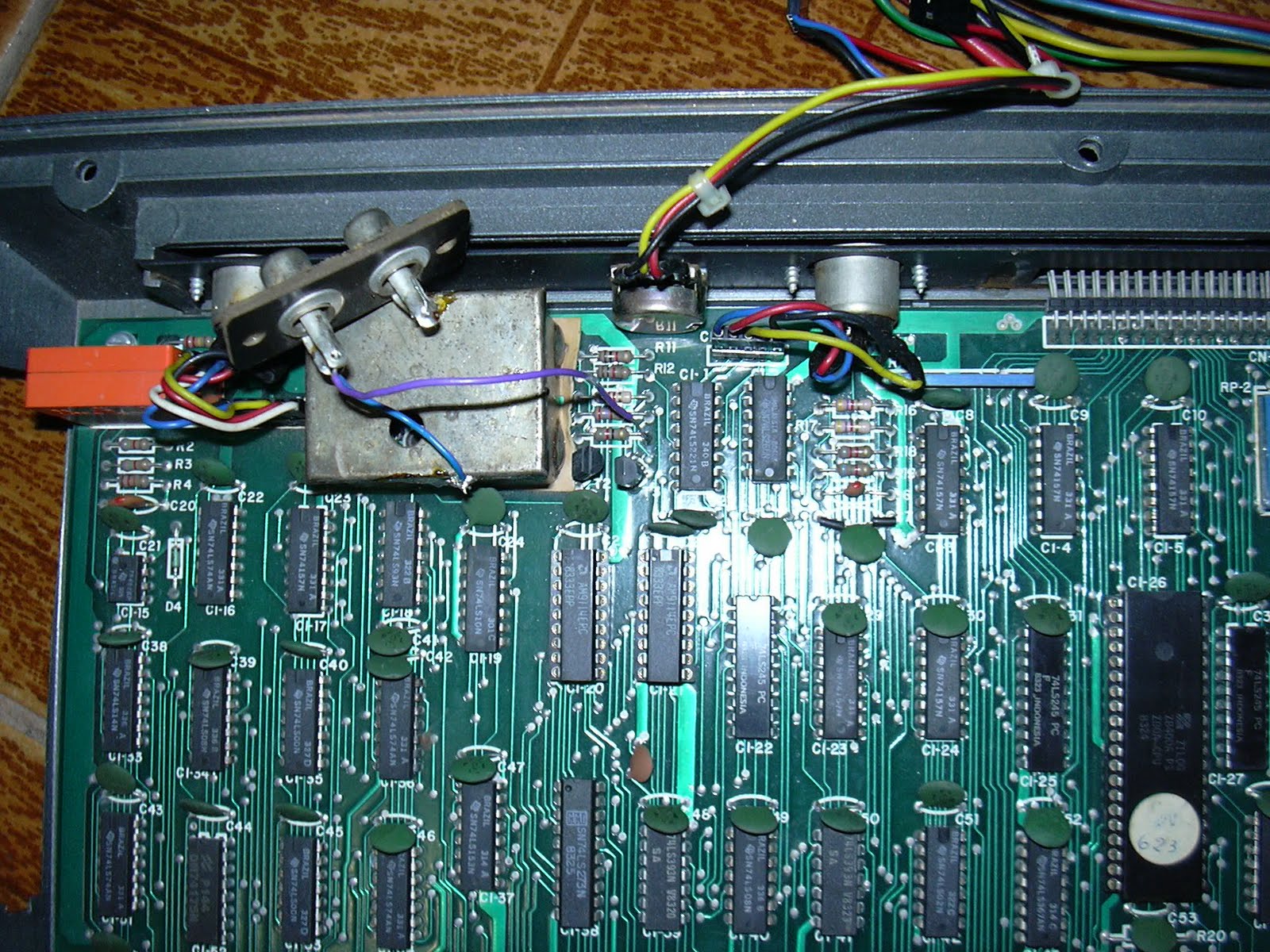
There's a tutorial that makes this TV output into a composite video output, which greatly improves the image, but requires some soldering skills.
My question is, without modding, can I use the Video output for composite (or even component) video? If yes, what would be the correct pin scheme?
Here's a picture of the back showing every input and output (the whole computer except for the PSU is inside the keyboard):
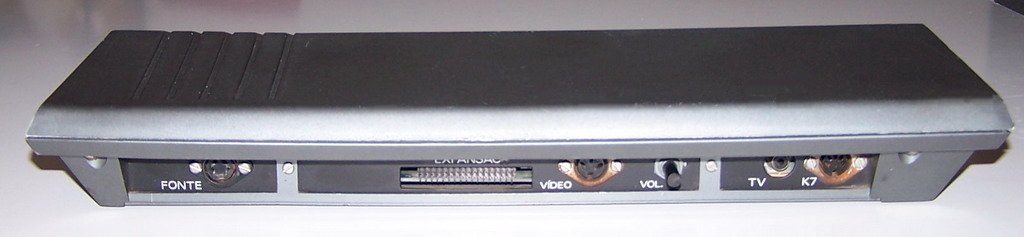
cp-300%20%28back%29.jpg

Reply 1 of 12, by Horun

User metadata
Rank l33t++
Rank
l33t++

My guess is that the video out could be composite but not sure why 3 pins, have seen some odd composite outputs that use a special cable to change a 4 pin into two RCA plugs (one for yellow Video, the other for Mono audio). Maybe the proper cable for that video out does same with a shared ground. Just guessing....

Hate posting a reply and then have to edit it because it made no sense 😁 First computer was an IBM 3270 workstation with CGA monitor. Stuff: https://archive.org/details/@horun

Reply 2 of 12, by filipetolhuizen

User metadata
Rank Oldbie
Rank
Oldbie

I came across this, but it's made for audio (vintage Grunding and Telefunken to be more exact). However for conduction purposes only, should work with video if pin scheme is the same:
s-l300.jpg

Reply 3 of 12, by cyclone3d

User metadata
Rank l33t++
Rank
l33t++

Easiest way to see what goes where would be to open it up and take a look.

My guess is that you will just short things out if you try to use the cable above.

From what I could find, that 3-pin output may be a monochrome output but couldn't find any actual information on the pinout. If it is a monochrome pinout, it may be fairly easy to convert the unit to have color output.

Really just need to open it up and see what is available.

Yamaha modified setupds and drivers
Yamaha XG repository
YMF7x4 Guide
Aopen AW744L II SB-LINK

Reply 4 of 12, by Horun

User metadata
Rank l33t++
Rank
l33t++
cyclone3d wrote on 2020-05-20, 01:25:
Easiest way to see what goes where would be to open it up and take a look. […]
Show full quote

Easiest way to see what goes where would be to open it up and take a look.

My guess is that you will just short things out if you try to use the cable above.

From what I could find, that 3-pin output may be a monochrome output but couldn't find any actual information on the pinout. If it is a monochrome pinout, it may be fairly easy to convert the unit to have color output.

Really just need to open it up and see what is available.

Good point ! I saw a similar three pin while googling and it went into a powered conversion box to convert video out but no good description, not for same unit but without knowing where those three pins come from could be a disaster if hooked up wrong.

Hate posting a reply and then have to edit it because it made no sense 😁 First computer was an IBM 3270 workstation with CGA monitor. Stuff: https://archive.org/details/@horun

Reply 5 of 12, by Volo

User metadata
Rank Member
Rank
Member

I found this article about the computer: http://v8bits.blogspot.com/2009/09/saida-vide … monitor-no.html
There is a nice pic of the port: http://1.bp.blogspot.com/_hK1-3x9rtf8/SrQceGH … 00/DSCN0274.JPG

Hope it helps. Brazilian "mystery IOs" may become a problem.

Want to play MS-DOS keyboard-only games with a gamepad? Feel free to purchase Volo's Pad-to-PS/2 by writing me an e-mail:
3hUGsDI.png

Reply 6 of 12, by filipetolhuizen

User metadata
Rank Oldbie
Rank
Oldbie
Volo wrote on 2020-05-20, 07:55:

I found this article about the computer: http://v8bits.blogspot.com/2009/09/saida-vide … monitor-no.html
There is a nice pic of the port: http://1.bp.blogspot.com/_hK1-3x9rtf8/SrQceGH … 00/DSCN0274.JPG

Hope it helps. Brazilian "mystery IOs" may become a problem.

These pictures are from the tutorial that converts the TV out to Composite Video out. Seems to be easy for those who are skilled on soldering.

cyclone3d wrote on 2020-05-20, 01:25:
Easiest way to see what goes where would be to open it up and take a look. […]
Show full quote

Easiest way to see what goes where would be to open it up and take a look.

My guess is that you will just short things out if you try to use the cable above.

From what I could find, that 3-pin output may be a monochrome output but couldn't find any actual information on the pinout. If it is a monochrome pinout, it may be fairly easy to convert the unit to have color output.

Really just need to open it up and see what is available.

The CP-300 is monochrome only, like the original TRS-80 (not the CoCo version).

Reply 7 of 12, by Vynix

User metadata
Rank Oldbie
Rank
Oldbie

Perhaps one of the pins is for luminance (or Luma, aka "Y" in Y/C), another pin is for Audio then the rest should be ground.

You could try and poke around with an oscilioscope to find a potential video signal... But that's something that might be hard to grasp for some people.

Proud owner of a Shuttle HOT-555A 430VX motherboard and two wonderful retro laptops, namely a Compaq Armada 1700 [nonfunctional] and a HP Omnibook XE3-GC [fully working :p]

Reply 8 of 12, by mdog69

User metadata
Rank Newbie
Rank
Newbie
Vynix wrote on 2020-05-20, 23:22:

Perhaps one of the pins is for luminance (or Luma, aka "Y" in Y/C), another pin is for Audio then the rest should be ground.

You could try and poke around with an oscilioscope to find a potential video signal... But that's something that might be hard to grasp for some people.

The computer is a clone of a TRS80 Model 3, which in turn was a "all in one" version of the TRS80 Model 1. No sound, no colour, limited mosaic graphics (2×3 blocks in each character cell).

As far as I know most the closest thing to sound on a Z80 based TRS80 was by generating rf noise from the computer which was detected by an AM radio tuned to a quiet/empty frequency.

My money is on GND, +5V, and video. That would allow an external RF modulator to be powered directly from the computer. The Model 1 (5 pin DIN) had such an arrangement (UM1233 modulator in a small box).
I note that this computer already has a modulator built in, so its possible that the video connector simply has three pins because the 2 pin DIN connector is only ever used for speakers (slot+pin).

Personally I'd use a multimeter to determine the pins by measuring the voltage, noting that on a digital multimeter a +5v source will be immediately obvious, and video signal will show as a weak voltage source. (Use a multimeter set to a 10V DC range, do not use a moving coil meter also known as (aka) "a meter with a needle").

Reply 9 of 12, by filipetolhuizen

User metadata
Rank Oldbie
Rank
Oldbie

Sound is played through an internal speaker (the volume knob on the back controls it) which can also play digitized voices:
https://www.youtube.com/watch?v=4M3xs3vOu7M
I'm guessing it's the same person who made the TV out to Composite out conversion tutorial as the image is incredibly clean in this TV and you can see he's using an A/V cable.

Reply 10 of 12, by Horun

User metadata
Rank l33t++
Rank
l33t++
mdog69 wrote on 2020-05-21, 07:11:
My money is on GND, +5V, and video. That would allow an external RF modulator to be powered directly from the computer. The Mode […]
Show full quote

My money is on GND, +5V, and video. That would allow an external RF modulator to be powered directly from the computer. The Model 1 (5 pin DIN) had such an arrangement (UM1233 modulator in a small box).
I note that this computer already has a modulator built in, so its possible that the video connector simply has three pins because the 2 pin DIN connector is only ever used for speakers (slot+pin). That would allow an external RF modulator to be powered directly from the computer. The Model 1 (5 pin DIN) had such an arrangement (UM1233 modulator in a small box).
I note that this computer already has a modulator built in, so its possible that the video connector simply has three pins because the 2 pin DIN connector is only ever used for speakers (slot+pin).

Personally I'd use a multimeter to determine the pins by measuring the voltage, noting that on a digital multimeter a +5v source will be immediately obvious, and video signal will show as a weak voltage source. (Use a multimeter set to a 10V DC range, do not use a moving coil meter also known as (aka) "a meter with a needle").

Wow "the My money is on GND, +5V, and video" and "That would allow an external RF modulator to be powered directly from the computer. ". That explains what I saw in google search, think it was a Model 1 (but could be wrong) but that does make sense with what I saw when searching for info. Thanks
Sorry can not add anything extra to help.

Hate posting a reply and then have to edit it because it made no sense 😁 First computer was an IBM 3270 workstation with CGA monitor. Stuff: https://archive.org/details/@horun

Reply 11 of 12, by Volo

User metadata
Rank Member
Rank
Member

As you may see on the pictures - there are 4 different wires. They may quite be
1. Shield Ground
2. Signal Ground
3. VCC, and
4. Composite.

But since this thing came with it's own monochrome monitor - it may quite be:
1. Ground,
2. H sync,
3. V sync, and
4. Signal.

You still need an oscilloscope to figure it out.

Last edited by Volo on 2020-05-30, 20:25. Edited 1 time in total.

Want to play MS-DOS keyboard-only games with a gamepad? Feel free to purchase Volo's Pad-to-PS/2 by writing me an e-mail:
3hUGsDI.png

Reply 12 of 12, by rmay635703

User metadata
Rank Oldbie
Rank
Oldbie

That appears to be identical to the common 5 wire color analog cable I have.

Only way to know is to put probes on each wire or open er up and see where the pins go

Ground and 5v is easy to ID,

Good luck