VOGONS


First post, by LewisRaz

User metadata
Rank Member
Rank
Member

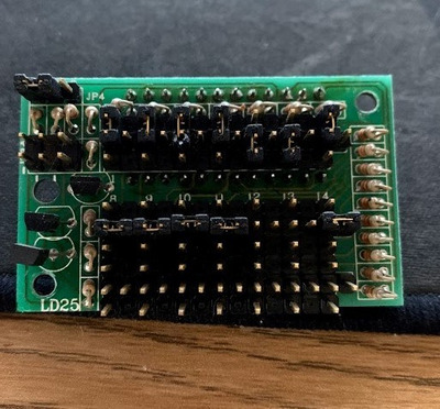
Hello all. I have this turbo lcd display that I want to set up.
The motherboard has a 3 pin turbo switch header and I have a switch on it and the turbo function itself works.
It also has a 2 pin turbo LED header.

I am guessing from looking at others that 2 pins will be for power. 2 will connect to the motherboard header and the final 2 will go to the turbo LED.

I do not own a multimeter to test however so was wondering if anyone had encountered one like this before?

It does not seem to be any from this list:

http://www.minuszerodegrees.net/led_speed_dis … eed_display.htm (This site appears to be down right now)

Forgive me is this is a simple question but I have not messed with one of these before and do not want to break it.

Cheers

Attachments

  • IMG_3296.jpg
    Filename
    IMG_3296.jpg
    File size
    71.81 KiB
    Views
    361 views
    File license
    Public domain

My retro pc youtube channel
Twitter

Reply 1 of 7, by PARKE

User metadata
Rank Oldbie
Rank
Oldbie

There are threads about these displays every couple of months but I cannot rember this one. It seems there are more different types out there than listed on the minuszerodegrees site.
Usually when there are 4 sets of connectors like as on top left in your sample then the connector with three pins (high-common-low) is meant to be connected to the turbo switch. For this type of setup the turbo switch has 2x3 sets of wires:
http://www.suntekpc.com/htm-2/power-switch-pu … urbo-3p3c-2.htm

The three connectors with 2 pins each are then meant for 5v power, turbo led on frontpanel, and power led on front panel.
Aren't there any markings next to these three connectors ?

Last edited by PARKE on 2020-05-22, 11:59. Edited 1 time in total.

Reply 3 of 7, by LewisRaz

User metadata
Rank Member
Rank
Member

Thanks for the replies. I have thrown together this extremely high tech diagram of what I can see.
I have a basic understanding of electronics but nothing like the brains on this forum! probably simple for some.

Seeing as I have positive and negative marked and 2 of the sets are joined that this I can narrow it down to 5050. Someone who understands these components better will probably think it is obvious now.
I am thinking it is the end 2 pins for power as they feed into the transistors and also some common rails across the bottom jumpers?

The bridged ones could be for 2pin LED input signal from motherboard and the turbo LED on the case? (another 2 pin).

This is the logic my brain is seeing.. I am happy to be corrected however!

EDIT: Just for clarity the red lines are traces, not jumpers.

Attachments

  • turbo.png
    Filename
    turbo.png
    File size
    14.3 KiB
    Views
    315 views
    File license
    Public domain

My retro pc youtube channel
Twitter

Reply 4 of 7, by PARKE

User metadata
Rank Oldbie
Rank
Oldbie
LewisRaz wrote on 2020-05-22, 12:23:

The bridged ones could be for 2pin LED input signal from motherboard and the turbo LED on the case? (another 2 pin).

I have a display with a similar set of 4 connectors (see photo) and in combination with a later 486 mobo only the 3-pin turbo switch connector (red-black-white) and the 2-pin 5volt connector (green-black) are needed because both the frontpanel power led + turbo led get their juice straight from the mobo.

inside.jpg
Filename
inside.jpg
File size
111.67 KiB
Views
306 views
File license
Public domain

Reply 5 of 7, by LewisRaz

User metadata
Rank Member
Rank
Member

I have it powered!

And after some investigating it became pretty easy to set up!

For anyone discovering this thread in the future. My diagram and assumptions were correct.

My retro pc youtube channel
Twitter

Reply 7 of 7, by LewisRaz

User metadata
Rank Member
Rank
Member

Cheers. For reference J4 seemed to toggle a permanent display(turbo switch had no effect on it) or the other position where it would toggle with the switch.

The actual display segments were similar to this: http://www.minuszerodegrees.net/led_speed_dis … 20-%20S-501.jpg

Although the positions did not mean the same as that. It was not difficult to work out what each position did.

My retro pc youtube channel
Twitter