VOGONS


First post, by 386SX

User metadata
Rank l33t
Rank
l33t

Hi,

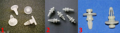
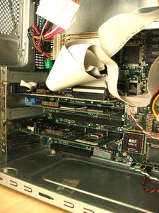
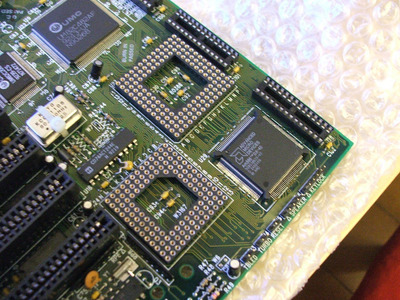
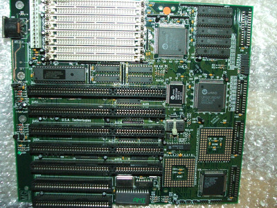
EDIT: I've just received my 386 mobo, a MG-38606 equivalent QD-U386DX and cause I can't find an AT case like I'd like or at good price, I'll use it in a ATX case as bad as it will look like for a time correct machine. Having tried with Socket 7 pentium1 mobo I've seen some holes in the case are equal others not. How would you fix it? with those plastic clip to have some space but still it would only be pushed to the case with a couple of screws only on the left side...
EDIT: five holes are ok on the mainboard with the metal spacer so I will need just a couple of plastic ones. 😉
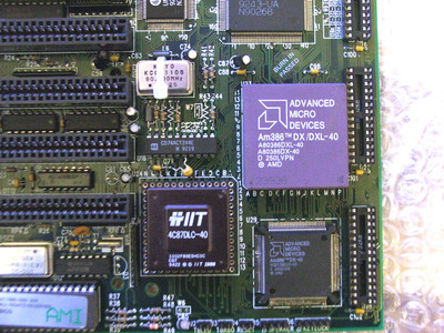
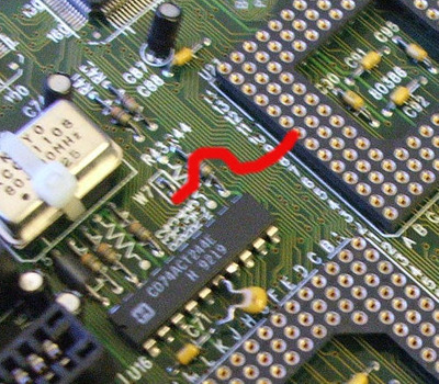
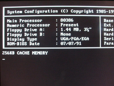
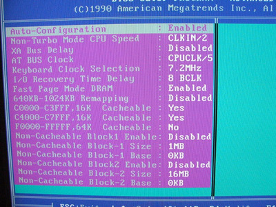
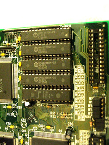
Now let's ask some opinions, what do you think about the board? (I uploaded better photos with cleaned pcb)

Thanks

Attachments

  • mainboard_386_3.JPG
    Filename
    mainboard_386_3.JPG
    File size
    237.3 KiB
    Views
    841 views
    File license
    Fair use/fair dealing exception
  • mainboard_386_2.JPG
    Filename
    mainboard_386_2.JPG
    File size
    376.36 KiB
    Views
    842 views
    File license
    Fair use/fair dealing exception
  • mainboard_386.JPG
    Filename
    mainboard_386.JPG
    File size
    433.4 KiB
    Views
    847 views
    File license
    Fair use/fair dealing exception
Last edited by 386SX on 2020-06-12, 15:52. Edited 14 times in total.

Reply 1 of 16, by konc

User metadata
Rank l33t
Rank
l33t

The general idea is something like this:
-make sure your case supports AT layout, most if not all older ATX cases do so, modern cases don't anymore
-use screws on all metal-covered holes of the m/b that align with the case's metal stand-offs. Not all will align, at least 2 on the back side and 1 more somewhere else will though. Might be a lot more depending on the case and m/b but 2+1 is enough
-use plastic stand-offs/spacers on the remaining holes that don't align to prevent bending when working on the motherboard
#1 (or similar) for m/b holes that don't align with any case hole, #2 for not metal-covered m/b holes that align with case holes where you can screw a stand-off and #3 for m/b holes that align with case cuts where you can slide this type of stand-off

In any case if the AT layout is supported don't worry too much, you will be able to securely mount it

ps.png
Filename
ps.png
File size
256.7 KiB
Views
861 views
File license
Public domain

Reply 2 of 16, by 386SX

User metadata
Rank l33t
Rank
l33t
konc wrote on 2020-06-10, 11:37:
The general idea is something like this: -make sure your case supports AT layout, most if not all older ATX cases do so, modern […]
Show full quote

The general idea is something like this:
-make sure your case supports AT layout, most if not all older ATX cases do so, modern cases don't anymore
-use screws on all metal-covered holes of the m/b that align with the case's metal stand-offs. Not all will align, at least 2 on the back side and 1 more somewhere else will though. Might be a lot more depending on the case and m/b but 2+1 is enough
-use plastic stand-offs/spacers on the remaining holes that don't align to prevent bending when working on the motherboard
#1 (or similar) for m/b holes that don't align with any case hole, #2 for not metal-covered m/b holes that align with case holes where you can screw a stand-off and #3 for m/b holes that align with case cuts where you can slide this type of stand-off

In any case if the AT layout is supported don't worry too much, you will be able to securely mount it

ps.png

Thanks, I suppose the first and second are the ones I need cause it's not so old to have the third image spacers. I'm going to look them on ebay. I've updated the thread cause I've just received the board! 😁

Reply 3 of 16, by 386SX

User metadata
Rank l33t
Rank
l33t

First of all I've to cover those two traces that has been already exposed to check their integrity and I've already ordered the green uv curable paint. Then I'm going to solder a Ni-Mh battery on this and study how to install it on a P4 atx case I've already used for my P75 build.
Then I've to understand jumpers that beside the cache ones there're two related one W4 for the npu, one W7 already factory shorted and not changable and W6 that is opened but may be cpu related.
I hope I'm not going to ruin anything installing a PGA socket cpu.

Good news in the atx case five holes can be fixed with screws three of them with metal supports, for the other two I don't know where to find those plastic things above, I might use some plastic between the metal and the screws (?). The other problem is the center hole that would need to be built in the back of the case and the up-right angle where there's a big space left below.
Question: just to be extra safe this would be the correct cpu and fpu position right? The round sign on the cpu and fpu directed to the angle of A and 1 pins? Also for the fpu is it right to have ONE line of pins so the first pin would start from 2 and B pins? 😀

Attachments

  • mainboard_386_4.JPG
    Filename
    mainboard_386_4.JPG
    File size
    359.15 KiB
    Views
    819 views
    File license
    Fair use/fair dealing exception
Last edited by 386SX on 2020-06-10, 18:33. Edited 2 times in total.

Reply 4 of 16, by imi

User metadata
Rank l33t
Rank
l33t
386SX wrote on 2020-06-10, 12:23:

I hope I'm not going to ruin anything installing a PGA socket cpu.

I wouldn't risk it, and even then, what are you trying to achieve by installing the same CPU in PGA that is already on the board?

Reply 5 of 16, by 386SX

User metadata
Rank l33t
Rank
l33t
imi wrote on 2020-06-10, 13:20:
386SX wrote on 2020-06-10, 12:23:

I hope I'm not going to ruin anything installing a PGA socket cpu.

I wouldn't risk it, and even then, what are you trying to achieve by installing the same CPU in PGA that is already on the board?

I hope they didn't put a socket there without some sort of option for it, I'd not understand this. 😀 The idea would be to have an alternative for example for the Cyrix DLC I have. (also I really don't like those plastic cpus, they looks so cheap and low end..the ceramic one is all another world imho 😁). But before I'll try without both and see in the bios if there're any options related. The position of both cpu and fpu in that way would be correct? The fpu must stay in the center?

Reply 7 of 16, by 386SX

User metadata
Rank l33t
Rank
l33t
imi wrote on 2020-06-10, 13:41:

to me it feels more like the soldered CPU was "optional"
I've seen boards with upgrade sockets before, but this seems to be either or to me.

In other images of the equivalent QD mainboard sure the fpu socket was there but there're photos of both versions with or without the cpu pga socket and/or without the soldered one. Also there're components inside the cpu socket I wonder what they would install them for if the socket wasn't there for some reason. Maybe in the bios there's some option to enable or disable it. There's a W7 jumper and a W6 jumper that are interesting in some version there's the jumper to close or open other times like mine both are factory fixed, one close the other opened and cannot be modified. I suppose reading somewhere that for the FPU part it may be needed to set a 33Mhz FPU, in fact the traces seems to go inside the FPU socket. The other closed W7 jumper it's not clear but EDIT: is probably related to the coprocessor error signal to A8 pin of the PGA socket.
I'm not going to risk now for sure but I want to know if I'll be able to use the Cyrix on this. Maybe from the bios once I'll solder the battery I'll have more info on it.

Last edited by 386SX on 2020-06-10, 16:21. Edited 1 time in total.

Reply 8 of 16, by 386SX

User metadata
Rank l33t
Rank
l33t

I found in a DOS game german forum a thread on another identical mainboard build by another manufacturer and there're some useful info there. It seems the board of that user has both the socket and the soldered cpu and same jumpers. It looks like it actually had problem with L2 cache but in the meanwhile it said that one jumper (I suppose the W4 one on the mainboard) seems to enable the FPU and in the bios there's the Weitek option for who has that.
Still I'm not entirely sure about the W7 (factory closed in my case) and W6 (factory opened) jumpers. In its case both the W7 and W6 are opened while in mine the W7 is close but both has the DX40. Maybe it's really something to do with the cpu socket option.

Here there's another found identical equivalent layout Magitronics A-B341H and the W4 is written to be the NPU enabling jumper so the others two remains to understand.

https://stason.org/TULARC/pc/motherboards/M/M … 86-A-B341H.html

Last edited by 386SX on 2020-06-10, 14:53. Edited 1 time in total.

Reply 10 of 16, by 386SX

User metadata
Rank l33t
Rank
l33t
chrismeyer6 wrote on 2020-06-10, 14:52:

That board looks to be in great shape. Very much looking forward to seeing the finished system.

I'll not be happy until I'll find a compact AT horizontal case with led freq hole. The idea of installing it in an ATX case make me sad but right now I can't buy it beside not even I can't find one that looks as I would. 🙁

Reply 11 of 16, by 386SX

User metadata
Rank l33t
Rank
l33t

Interesting and strange.. the W7 jumper that in my case seems to be factory closed with a piece of metal, looks like the lower side is connected on the bottom layer to the A8 pin of the PGA132 cpu socket. If I'm correct that would be the ERROR# pin.. what should it suppose to mean? In all the images I see it's opened. Is it possible or I am wrong?

EDIT: I think to understand it should be related to the "Coprocessor Error" is a level sensitive input signal gate that make the cpu do eventually some exception. Correct me if I'm understanding this wrong. So I suppose that is co-processor related and may or not be needed in some revision or depends on the model of co-cpu installed. It looks like it's more software oriented at the end and anyway may not be interesting right now.

Attachments

  • W7jumper.jpg
    Filename
    W7jumper.jpg
    File size
    83.62 KiB
    Views
    744 views
    File license
    Fair use/fair dealing exception

Reply 12 of 16, by 386SX

User metadata
Rank l33t
Rank
l33t

Some update:

The board boot! And with the IIT only FPU an no PGA cpu, only the already soldered one (and the W4 jumper shorted), it shows "Numeric processor: present" in the bios post. I've tried without any battery because I wanted to understand the voltages to the battery poles. Something I don't understand... if the jumper W1 that is based on three pins and default was 1-2 shorted from the left, in that case the Ni-Cd/Ni-Mh pcb point get almost 5 volts while the external barrel connector almost 0,5 volt or less. There's no others jumper for the external battery so I suppose the W1 in the position all opened or 2-3 shorted should switch to the external battery but the higher voltage on the external battery is something like 2 volts, certainly not able to charghe a 3,6 volts battery. What do you think maybe the external battery was intended to be not rechargable? I think I'll solder the usual 3,6v (3x1,2) Ni-Mh rechargable battery directly on PCB beside I already prepared one for the external four pin connector.
Another strange thing how the IIT 40Mhz FPU stay almost cold even if the post message make me think it is seen and I installed is as the image above in the center of the Weitek socket with the external one line of pin empty and with the round key in the direction to the angle between A and 1 beside obviously it is not its first pin. But I think I remembered it got hot during running, maybe I don't remember well or I've to test it in some bench, but I'm still far from benchmarks.

Reply 13 of 16, by 386SX

User metadata
Rank l33t
Rank
l33t

Some updates if anyone cares:
hard disk arrived a Seagate 545MB of the 1996 and the uv curable trace pcb paint and so I began to install it in the atx case until I'll find an AT one. I used this specific pcb green mask paint on the traces that were a bit exposed under the battery but was done only to check them so they only needed a new layer and now they are green as before (more or less) but most important they are safe from external contact. I soldered a charged Ni-Mh 80mah three cells battery and now the board boot and mantain the config! Installed the mb in the atx cases, five holes (left and bottom) are secured but the others (up-right or center) cannot so I used some rubber distancer to level the mobo to exclude bending it to the case metal but I can't do nothing for the opposite forces (for example when I've to remove a ISA card the mobo moves a bit).Anyway seems enough stable for now. The config is this:

MG 38606 UMC481/482 chipset mobo
Soldered Amd 386DX-40
IIT 4C87DLC-40
256Kbytes of 15ns cache
16MB 60ns SIMM (4x4MB) FPM
Cirrus Logic GD-5429 1MB DRAM ISA
Yamaha YMF719E ISA sound card
Winbond W83757AF/W83758AP I/O ISA card
Seagate 545MB IDE disk
Philips CDRW 2400 cd drive

I had some problems with the I/O controller. Three of the one I have (at least one I'm sure it was working, I suppose UMC based) can't boot the whole pc finally and fortunately I found this Winbond based card that is accepted by the board. I have a Glodstar Prime 2C and a TK UMC82C863F/82C865F and both can't boot, I'm sure the first always ran ok. Who knows why..
Now, before installing any o.s. I'd like your opinion on how to optimize that page of the bios and some idea to how to fix the mobo without the clips (i should make new holes for that and I can't find anyway plastic distancers).
Some news also on the jumpers I've found an hidden jumper W2 that seems connected to the keyboard bios AMI chip.. what would you think it may be needed?
Some photos:

Attachments

  • 386_ATX_2.JPG
    Filename
    386_ATX_2.JPG
    File size
    68.84 KiB
    Views
    667 views
    File license
    Fair use/fair dealing exception
  • 386_ATX_1.JPG
    Filename
    386_ATX_1.JPG
    File size
    116.92 KiB
    Views
    667 views
    File license
    Fair use/fair dealing exception
  • 386_ATX_3.JPG
    Filename
    386_ATX_3.JPG
    File size
    79.68 KiB
    Views
    667 views
    File license
    Fair use/fair dealing exception
  • 386_ATX_4.JPG
    Filename
    386_ATX_4.JPG
    File size
    151.46 KiB
    Views
    667 views
    File license
    Fair use/fair dealing exception

Reply 16 of 16, by 386SX

User metadata
Rank l33t
Rank
l33t

Today happened the strangest thing. The board since I booted seems that was a bit unstable. At first I was blaming the floppy disks I have mostly gone, then I was thinking I was using too fast caches (15ns vs the 20ns of the specifications), then I was thinking to some incompatibility with different isa cards.
But today the vga output began to be darker almost not visible! Changed different vga and same thing!
Tried changin cache, removing everything even the board from the case, nothing. At the end do you know what it solved back the situation to the normal vga signal? Using a original AT psu! I suppose even if I can't imagine why, the ATx to AT converter without the -5v or the psu I'm using (is a still good Enermax one with very stable 5,0 and 3,3 volts but lacking the -5v) was the problem.
So I've to pause the project while searching for an AT case and maybe finding a good AT psu or cleaning and checking the one I've that is far from "high end" (thin wires, few components..). Another AT psu I tried first (on another mainboard fortunately, like I was already looking at the future...) once pushed the power button did " a bad light and sound" as usually when capacitor are gone badly. I've still to check it inside but I'm sure it was ok some time ago...
There's no way with old AT psu it always get scaring to power boards or components you care about.

But before stopping the project I did some tests:

3DBench: 15,8
Speedsys: CPU 6,33 / Vesa mem: 3667 Kb/s / L2-256Kbytes: 27,41 Mb/s / Main memory: 12,39 Mb/s
Cachechk: 256Kb L2: 27,8MB/s Main mem: 9,4MB/s Ram access read: 222ns Ram access write: 104ns
Quake did run so I suppose the IIT FPU is running ok! 😁