VOGONS


First post, by Deksor

User metadata
Rank l33t
Rank
l33t

I just started experimenting with solutions to fix old motherboards batteries but I encountered several issues which may me wonder if it is as easy as some people may say it is.
For now I have tested this on only two motherboards, but both reacted more or less the same.

First we have this 12MHz 286 motherboard :
fB4mUoNl.jpg?2
x6tf8apl.jpg?2
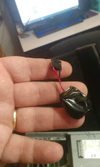
I tried both external and internal options (always CR2032 based).

So what's the problem you may say ?

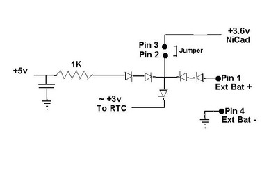
Well the battery is brand new (I can measure 3.2V), but when adding a diode, the voltage drops ... and the RTC chip is only powered with 2.3V.
This is ok to save the BIOS features, but time doesn't tick at all. It's stuck the moment I stop the computer.

I managed to hack the circuit so the 5V current just never tries to go in the battery at all, rendering the use of an extra diode useless, and the RTC chip is now powered by 2.7V. This is enough for the time keeping ...
But this also means the lifespan of the timekeeping will be shortened, right ?

The same problem appears with external battery holders, but fortunately the battery holders I bought can fit 2 batteries, so the RTC chip ends up being powered with 5.5V. A bit overpowered I think, but nothing to worry about I think.

Then I tried it on my Abit FU333
2AKVn50l.jpg
vYWRJ1Al.jpg

But then angain, the same problem appears ... 2.4V in the RTC circuit ... And here I can't think of a way to even "hack" it to spare an extra diode ... Meaning I can only rely on using two external CR2032.

Have anyone experienced this problem ? Do you have any ideas of how to overcome this (other than putting a new varta battery) ? I tried super capacitors in the past, but the time keeping problem appeared too very quickly.

Trying to identify old hardware ? Visit The retro web - Project's thread The Retro Web project - a stason.org/TH99 alternative

Reply 1 of 6, by MMaximus

User metadata
Rank Oldbie
Rank
Oldbie

Sorry to hear this particular board is proving to be more difficult than you expected. It seems a lot of you guys seem to like the challenge of replacing barrel batteries with either new ones or CR2032... Personally I'm all in for using external battery packs and not having to solder anything! I've managed to make every board that had a suitable connector work thanks to a 3xAA or 3xAAA pack (and I've tried with maybe 15-20 boards ranging from 286 to 486.) Only once have I encountered the problem of the clock not ticking when powered off, and I assumed it was due to a faulty crystal.

Hopefully you'll be able to make this board work!

Hard Disk Sounds

Reply 2 of 6, by Horun

User metadata
Rank l33t++
Rank
l33t++
MMaximus wrote on 2020-07-11, 20:02:

Sorry to hear this particular board is proving to be more difficult than you expected. It seems a lot of you guys seem to like the challenge of replacing barrel batteries with either new ones or CR2032... Personally I'm all in for using external battery packs and not having to solder anything! I've managed to make every board that had a suitable connector work thanks to a 3xAA or 3xAAA pack (and I've tried with maybe 15-20 boards ranging from 286 to 486.) Only once have I encountered the problem of the clock not ticking when powered off, and I assumed it was due to a faulty crystal.

Hopefully you'll be able to make this board work!

Me too ! I prefer to use externals on all the XT, 286, 386 that had a barrel battery and have the ext. header. Have read that Tunnel/Schottky diodes have a much less V. drop (~.2-.3v, similar to In34 Germ. type) at the typical 10uA draw of most CMOS, better than standard In4001 silicon type diodes of .7v drop

Hate posting a reply and then have to edit it because it made no sense 😁 First computer was an IBM 3270 workstation with CGA monitor. Stuff: https://archive.org/details/@horun

Reply 3 of 6, by Jo22

User metadata
Rank l33t++
Rank
l33t++

I think the same. Germanium diodes have little voltage drop (~0.2V) and were often used in crystal radios.

"Time, it seems, doesn't flow. For some it's fast, for some it's slow.
In what to one race is no time at all, another race can rise and fall..." - The Minstrel

//My video channel//

Reply 4 of 6, by Deksor

User metadata
Rank l33t
Rank
l33t

This is very interesting !
Sure I can do the external battery mod, but I feel like the internal mod is more convenient in the end when dealing wiht the motherboard itself though this is just my personal opinion.
Are the germanium diodes still made ? can see lots on ebay and such, but I feel like they could easily be fakes x)

What kind of diode would you recommend the most ? Any of them as long as they have a smaller drop ?
Can I replace other diodes that end up in the circuit to reduce even more the voltage drop ?

Trying to identify old hardware ? Visit The retro web - Project's thread The Retro Web project - a stason.org/TH99 alternative

Reply 5 of 6, by Horun

User metadata
Rank l33t++
Rank
l33t++
Deksor wrote on 2020-07-11, 21:41:
This is very interesting ! Sure I can do the external battery mod, but I feel like the internal mod is more convenient in the en […]
Show full quote

This is very interesting !
Sure I can do the external battery mod, but I feel like the internal mod is more convenient in the end when dealing wiht the motherboard itself though this is just my personal opinion.
Are the germanium diodes still made ? can see lots on ebay and such, but I feel like they could easily be fakes x)

What kind of diode would you recommend the most ? Any of them as long as they have a smaller drop ?
Can I replace other diodes that end up in the circuit to reduce even more the voltage drop ?

Yes you should be able to swap out one of the other diodes once you draw up the schematic of the circuit. On one of my very cheaply built old soc 3 - 486 it has a very simple resistor + diode circuitry for the batteries. It used a 3.6v NiCad (not rechargeable Lithium) so did not need a transistor based V & I limiting circuit to charge the NiCad. I attached how it runs, it has 5 diodes but it is a bit diff than many others. It looks like you could have 4 native diodes around the Batt + Cmos RTC feed from the picture. I would check to see your circuit is like in my ugly drawing..if your D1 does feed the CMOS (it appears to) then it could be swapped out with a Germanium or Schottky to gain about .3v more feed and still protect the circuit. .if the Tranny below batt is connected that would be for V+I limiting in the charge circuit to old battery.
edit fixed a boo-booo

Attachments

Hate posting a reply and then have to edit it because it made no sense 😁 First computer was an IBM 3270 workstation with CGA monitor. Stuff: https://archive.org/details/@horun

Reply 6 of 6, by candle_86

User metadata
Rank l33t
Rank
l33t

I use the similar method a laptop uses for mine, I take 2 cr2032, a speaker wire stripped and put red to + and black to - electrical tape it then heat shrink and then on my 386 I let it just sit on the board since it's a desktop not a tower. Works well, has the convince of cr2032 but connected to ext but comes out with the board. If you want to solder it I'm sure you could add a double cr2032 to attack to the external header

received_268293671130445.jpeg
Filename
received_268293671130445.jpeg
File size
145.2 KiB
Views
1647 views
File license
Public domain