Horun wrote on 2020-07-26, 02:40:
Good job ! Hope it is not a PLA, they generally cannot be replaced because there would be no documentation on how the array was originally programmed so you would not be able to program a replacement chip.
Yup its a PLA unfortunately when I checked the part code.
Looks like some proprietary logic programmed to it I guess?
The sticker may have some info surrounding this if we can locate the board manufacturer and find another board to read another PLA?
kalohimal wrote on 2020-07-26, 02:54:You need to be very careful when using this method, as if the current is too large, the trace might blow before the cap explodes […]
Show full quote
nzoomed wrote on 2020-07-25, 22:22:
Ok that sounds a good idea. I expect that there will be some that go hot or explode. If that is not going to damage the board, its probably the easiest way. My power supply also has a meter to display current draw.
You need to be very careful when using this method, as if the current is too large, the trace might blow before the cap explodes if it happens to be on a thin trace.
nzoomed wrote on 2020-07-26, 02:26:Yeah I wasn't too sure on what the current draw was supposed to be, but the cpu draws a good 1 amp alone. […]
Show full quote
Yeah I wasn't too sure on what the current draw was supposed to be, but the cpu draws a good 1 amp alone.
Just decided to pull out other chips to test things and it powers on with tbis chip removed, but no image on screen. Probably needs the chip for something important.
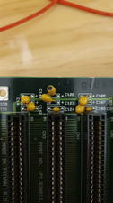
The sticker says C0080B on it.
The socket is labelled 16L8A on it, I will see what's written on the chip under the sticker.
Perhaps its just a dead chip?
You could put this chip back to confirm it is indeed causing the short. The 16L8A is a PAL chip and if it's bad it'll be really troublesome. You can replace it with a newer GAL chip, but you'll need to find a programmer and also the fuse map (JED) file. To get the JED file you'll need to find another identical board and read it from the same chip with the programmer.
Yes I accept it was a risky method, but did it any way.
All traces are OK.
Have since tested all the other caps and no shorts.
I think the PLA is the issue. Looks like there is not much I can do unless I can find another board identical?
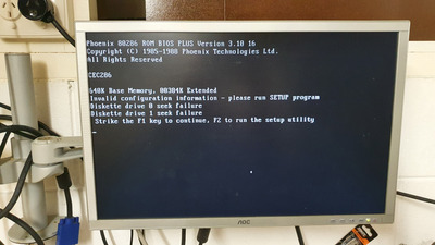
I was wondering if I dump the ROM chips that I might be able to find some info on the manufacturer if I opened them in a hex editor?
Looks like the BIOS is stored onn2 chips.