VOGONS


My Toshiba T3200 Luggable 286

Topic actions

First post, by steevf

User metadata
Rank Newbie
Rank
Newbie

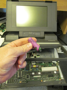
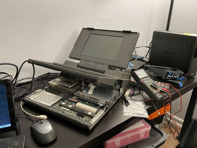
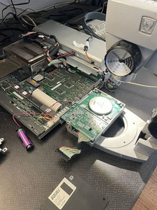
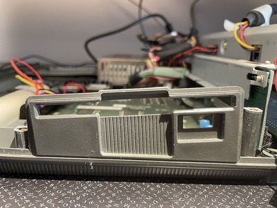
So, I have this "portable" computer that has been my daily driver from 1993 until around 1995.
And in 2020 it still works and on occasion I pull it out to do a bit of tinkering.
Both expansion ports are populated.
One with a VGA card so can use an external VGA monitor (the internal output is only EGA and the built in display is 4 shades of orange plasma).
The other one is a data acquisition/GPIO card in it for controlling external electronic projects.
I upgraded it with a 80287 FPU and maxed out the memory to 4 MB back in 1994.
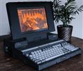
I was able to play The Catacomb Abyss 3D on this. I think the frame rate was about 6fps but it was 3D!

Anyway, some issues I would like to deal with. If anyone has some advice or resources I could check out please let me know.

Problem 1:
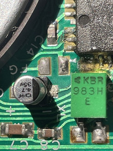
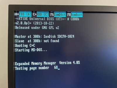
The HD. It's old and its only 40 MB and it's full. I installed WordPerfect 6.0 and it pretty much filled it up. (5.1 was much smaller) I would like to replace that old drive with some sort of SSD or CF. But finding a way to do that has been a challenge. I can't get any clear info on what the HD controller is. It's not IDE. But it also doesn't look like the MFM style. But I don't have as much experience with that.
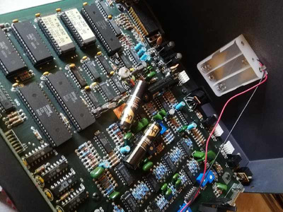
Problem 2:
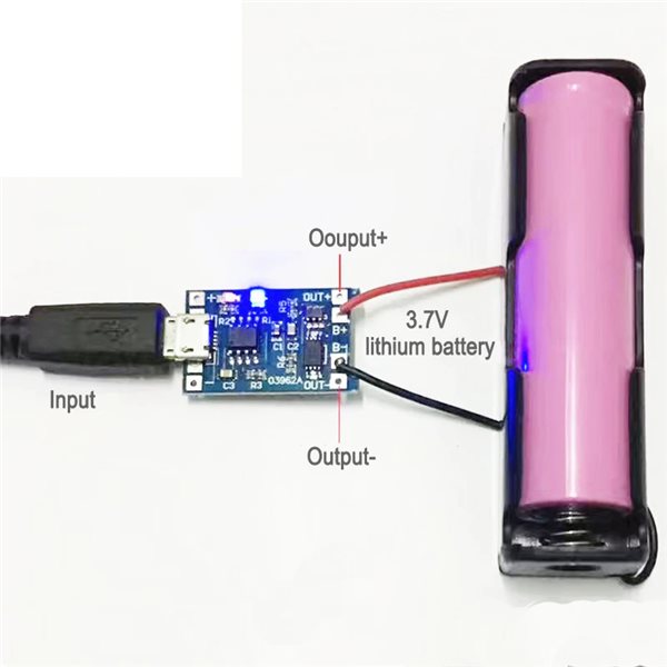
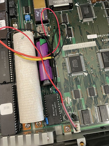
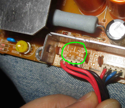
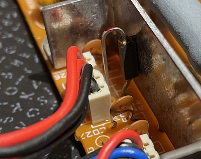
I want to find a more permanent solution to the CMOS battery. I've replaced it twice already and it's a real pain to get at it. And it needs a special 3.6v battery with leads soldered to a resister. (yeah I don't get it either, but that was what was in it. so I replaced it with the exact battery type every time. )
But the worst part about that battery is it will only last a few years and it's dead again.

IMG_0606cm.jpg
Filename
IMG_0606cm.jpg
File size
165.86 KiB
Views
1468 views
File license
CC-BY-4.0

Reply 1 of 45, by Tiido

User metadata
Rank l33t
Rank
l33t

I have one such machine too and I would love to see that memory expansion up close, since ideally I would like to make my memory own expansion.

The HDD you essentially cannot replace, the machine uses a custom controller and interface which is specific to it. If the HDD dies in some way the machine essentially bricks but it can sort of be worked around by removing the controller board. The BIOS will then complain that it cannot communicate to it but will let you boot, and something like XTIDE + sound card with IDE will let you use CF cards etc. I plan to do that sort of stuff in my T3200 and hack the BIOS so it wouldn't complain, and while at it, perhaps install batteries where the HDD used to be and make this an actual portable 🤣

For battery you'll want to have a double AA holder there instead, it'll last way longer.

T-04YBSC, a new YMF71x based sound card & Official VOGONS thread about it
Newly made 4MB 60ns 30pin SIMMs ~
mida sa loed ? nagunii aru ei saa 😜

Reply 2 of 45, by steevf

User metadata
Rank Newbie
Rank
Newbie

When I get the system on the bench again I'll get a shot of the memory expansion!

I have been looking at the 8bit-ISA to CF card from TexElec as a possible HD replacement.
https://texelec.com/product/lo-tech-xt-cf-lite-rev-2/
Not sure if that will work though and I don't have a clue how to hack the BIOS.

How exactly did you do the battery to make it last longer?

Reply 3 of 45, by Tiido

User metadata
Rank l33t
Rank
l33t

That would be great ~

That controller should work. The BIOS hack I mentioned is so far theoretical, one day when I get off my rear I'll do the IDE HDD/CF mod and will find the place in the BIOS that tries to deal with the existing HDD and do something about it. When will that happen I don't know.

Since the battery is not rechargeable and isn't being recharged you can simply attach a random 2x AA battery holder with two heavy duty AA in it on the connector wires instead of a 3V lithium. There'senough space to hide the battery pack in the machine, it'll last way longer though potential fallout from a bad AA is much worse than what a lithium battery is capable of...

T-04YBSC, a new YMF71x based sound card & Official VOGONS thread about it
Newly made 4MB 60ns 30pin SIMMs ~
mida sa loed ? nagunii aru ei saa 😜

Reply 4 of 45, by Jo22

User metadata
Rank l33t++
Rank
l33t++
Tiido wrote on 2020-08-13, 11:14:

[..] There'senough space to hide the battery pack in the machine, it'll last way longer though potential fallout from a bad AA is much worse than what a lithium battery is capable of...

Beware of carbon-zinc based AA batteries, though. They are lightweight, uncomplicated etc. but do leak quickly. It's part of their nature, in fact - they go "poof" (they dissolve) after just 1-2 years in some cases.
Lithium AAs can't handle overload or shorts, so they usually come with some internal protective circuits.
Alkaline AA batteries are properly the best compromise.

Edit: Please also be caredul with AA/AAA holders. The batteries often fall off the holder and roll all over the mainboards, destroying components.
Especially, if shipped from one place to another. I've seen that with several old computers and other devices (Pakratt PK-232 TNCs).
So I think that some piece of electrical tape or cable ties can help to prevent this.

Attachments

"Time, it seems, doesn't flow. For some it's fast, for some it's slow.
In what to one race is no time at all, another race can rise and fall..." - The Minstrel

//My video channel//

Reply 5 of 45, by steevf

User metadata
Rank Newbie
Rank
Newbie
Jo22 wrote on 2020-08-13, 11:29:
Beware of carbon-zinc based AA batteries, though. They are lightweight, uncomplicated etc. but do leak quickly. It's part of the […]
Show full quote
Tiido wrote on 2020-08-13, 11:14:

[..] There'senough space to hide the battery pack in the machine, it'll last way longer though potential fallout from a bad AA is much worse than what a lithium battery is capable of...

Beware of carbon-zinc based AA batteries, though. They are lightweight, uncomplicated etc. but do leak quickly. It's part of their nature, in fact - they go "poof" (they dissolve) after just 1-2 years in some cases.
Lithium AAs can't handle overload or shorts, so they usually come with some internal protective circuits.
Alkaline AA batteries are properly the best compromise.

Edit: Please also be caredul with AA/AAA holders. The batteries often fall off the holder and roll all over the mainboards, destroying components.
Especially, if shipped from one place to another. I've seen that with several old computers and other devices (Pakratt PK-232 TNCs).
So I think that some piece of electrical tape or cable ties can help to prevent this.

Good advice! Thank you.

I hope to be diving back into this project this year after I complete fixing my old Pentium system.

Reply 6 of 45, by tomdegerth

User metadata
Rank Newbie
Rank
Newbie

Hi all,
I too have a T3200 that I'm trying to get to run properly, currently waiting for a new lithium battery to continue the process.

I wanted to share a great article I found on the T3200, it covers a lot on the BIOS hack as well. You might have read it before, but here it is anyway;

https://medium.com/geekculture/the-luggable-l … 89-6d15ce56eadd

Best Regards,
Tom

Reply 7 of 45, by Jo22

User metadata
Rank l33t++
Rank
l33t++

Thanks for then link/article!

By the way, since it says "This is the Toshiba T3200SX from 1989 — a ‘luggable’ computer with 1MB of RAM,
40 MB HDD and a gorgeous 640x480 16-grey-shade gas plasma screen [..]" :

The picture viewer WinGIF has a special mode in which it chooses colors of the 16c VGA palette by their brightness levels in order to display grayscale pictures.

That only works with monochrome monitors, of course, or if the VGA card is in monochrome mode (remember the issue with the DDC pin on modern LCD monitors?).

"Time, it seems, doesn't flow. For some it's fast, for some it's slow.
In what to one race is no time at all, another race can rise and fall..." - The Minstrel

//My video channel//

Reply 8 of 45, by steevf

User metadata
Rank Newbie
Rank
Newbie

So, I back at this one. Working on several things at once.

1) Getting a new battery installed. I'm going to put the new one in a spring holder so I don't have to keep de-soldering the leads every time I replace it. I'm not sure if this is a regular thing with this or if there is something wrong with the computer but these batteries will only last a few years even if the computer is used. It's as if it still drains the battery while it's turned on. And these are hefty 2500mAh batteries too. Compare that with the typical CR2025 button battery at 200mAh that you would normally put in a computer.

2) I'm also trying to get the XIDE CF-lite card to work in it. So far when I put the card in, it will recognize it and even mount the 4 GB CF card (partitioned into three drives). But I can't get it to boot from it. The firmware in the XIDE is an older universal bios for XT computers. I tried to get a more up to date one designed for the 286 AT but the issue I run into is that I'm not able to run the BIOS flashing tools that I'm suppose to run to flash the new BIOS. Their instructions say to boot from a floppy disk. The only working floppy disk I have is on this computer but I actually don't have any floppy disks. So I'm a bit stuck there. I have an EEPROM programmer that I can use but the raw BIOS images they provide are not setup or configured or something. I could edit the binary image by had in the EEPROM programef if I new what bytes to place where, and that's just for the XIDE. After that I still don't know for sure how to handle the computer's BIOS itself to allow me to remove the HD and put in a CF drive or SD drive and still allow it to work.

2023-05-12 23.43.45 small.jpg
Filename
2023-05-12 23.43.45 small.jpg
File size
59.3 KiB
Views
1206 views
File license
CC-BY-4.0

Reply 9 of 45, by 16ShadesOfOrange

User metadata
Rank Newbie
Rank
Newbie

Hey guys, just ordered one of these beasts and been doing some research while I wait for it to arrive.

RAM
Hoping my rig will have the 3MB expansion board, will find out soon. I've been adding info to my github page, incl 3 pics of different RAM modules I've found online:

https://github.com/SpitFire-666/Toshiba-T3200

XT-IDE
- I have an XT-IDE CF ISA card that works in my T3200SX and T5200. I'll test it in the T3200 and let you know if it works.

CMOS Battery
- I wonder if you could use an 18650 (3.7v rechargeable battery)? If so, you could add a USB charging PCB (tiny and readily available ) then you could recharge it easily via microUSB (and mount a USB socket or cable)

6bd6b2a2-af43-4af0-b43f-b79c52b5963b.png

💻 Toshiba T5200 info
💻 Toshiba T3200SX info
💻 Toshiba T3200 info

Reply 10 of 45, by steevf

User metadata
Rank Newbie
Rank
Newbie

Thanks for posting your GitHub resource! That's going to be a great place to capture all of the diverse issues with these systems.

My current battery solution was to get the wires, resister, connector, and a removable battery holder in one peace, and it will actually fit just fine under the keyboard. This will make battery replacement easier as I don't have to disassemble the computer and solder wires together like it was originally built. The resister is hidden in the yellow shrink wrap.

2023-06-06 16.15.15 small.jpg
Filename
2023-06-06 16.15.15 small.jpg
File size
175.38 KiB
Views
1149 views
File license
CC-BY-4.0

I managed to get my BIOS files on a floppy disk from a different computer and was getting ready to try to update the XTIDE card BIOS when I found out my floppy drive was bad. I had read about this being common and sure enough, it appears to have been a bad cap. But the corrosion is bad enough it might not be an easy fix.

2023-06-06 15.20.33 small.jpg
Filename
2023-06-06 15.20.33 small.jpg
File size
172.23 KiB
Views
1149 views
File license
CC-BY-4.0

In fact if you looked closely( had a microscope 😀), you can see how the corrosion worked under the green coating and exited under the IC chip which wicked it on to all of the IC pins. While it was hard to photograph, it was clear to see in the microscope that all of the pins on the IC they were coated in bluish green oily residue.
That glue holding the big green box down might have helped minimize the damage elsewhere, it did partially dissolve the glue so the large green part is now free to move around. I'm worried about metal fatigue on the leads to the green part.

2023-06-06 14.38.28 small.jpg
Filename
2023-06-06 14.38.28 small.jpg
File size
148.72 KiB
Views
1149 views
File license
CC-BY-4.0

Because of the corrosion, I'm worried the capacitor replacement might not work, there might be too much other damage. Besides, I'm not really equipped to deal with SMT soldering as I don't have steady hands. The other option is to replace it with a new drive (new old stock I found on ebay) and build a custom cable for it from this thread: IanB's cable mod. Someone on reddit mentioned that cable working on the T3200 for the floppy. And then I found this: FlexiDrive Cable Adapter Which looks promising.
Not really sure if it will fit precisely as the board might be intended for the FlexiDrive floppy disk drive emulator and there is go guarantee that a standard floppy drive is going to place the connector is the exact right location. But since they did specifically mention the Toshiba computers in the description there is hope.

Because the facade for the floppy drive is actually part of the computer shell on the T3200, I would rather just have a working internal floppy drive than have to cut into the plastic to make an emulator fit no matter what the emulator is. FlexiDrives are too expensive anyway. I can always make the Gotek drive an external drive plugged in the parallel port in the back.

2023-06-06 16.22.58 small.jpg
Filename
2023-06-06 16.22.58 small.jpg
File size
205.67 KiB
Views
1149 views
File license
CC-BY-4.0

There is just no way to cut this down and still make it look good. 🙁

Reply 11 of 45, by steevf

User metadata
Rank Newbie
Rank
Newbie

So I've got the XTIDE with a CF card install and booting. The trick to getting it to boot to the CF card is to make sure the HD is disabled in the main CMOS by using the setup program TEST3.EXE. Just select the "0" option when it prompts for the hard drive. I had already installed DOS to the CF card from another computer and it just worked. The XTIDE bios was the default that came with the card, 2.0.0ß3+ (2013-10-22). Although I'm still going to get it updated when I finally get the new floppy drive installed. I also removed the power from the HD so that it doesn't continue to put any more wear and tear on the drive but mainly to spare my hearing from the rather obnoxious wine the drive makes. (It's the normal sound of HDs but I'm really, really, annoyed by it and I often would wear head phones to try to reduce the pain to my ears.)

2023-06-08 21.02.19 small.jpg
Filename
2023-06-08 21.02.19 small.jpg
File size
103.8 KiB
Views
1126 views
File license
CC-BY-4.0

I did manage to copy everything off the drive earlier using a parallel link cable and the DOS 6 intersvr/interlnk, so I'm ready to let the original HD sleep indefinitely even though the drive has low hours on it. I tried using laplink but I just couldn't get it to work, but DOS 6 interlnk worked just fine. That's weird because I was using Laplink branded Radioshack link cable and my understanding is the wiring would be slightly different in that the DOS interlnk used a few less lines so interlnk would always work with laplink cable but laplink wouldn't work with an interlnk cable.
EDIT: So it wasn't Laplink branded. I made a mistake. I pinned it out and found out it is not connected the same way as a Laplink cable. I wonder what happened to my Laplink cable. 🙁

Anyway, I digress. The new floppy drives have arrived and I'm just waiting on the supplies I need to make the cables. Hopefully by this weekend.

Reply 12 of 45, by steevf

User metadata
Rank Newbie
Rank
Newbie

The computer suddenly stopped working. It appears I lost the 5V rail on the power supply or something has shut it down. 12V is fine. Looks like I'm dead in the water with this one.

Reply 13 of 45, by Tiido

User metadata
Rank l33t
Rank
l33t

The PSU is full of bad RIFA capacitors and all of them will need replacing. I think there were fuses in the PSU on every rail, they are worth checking out too. My T3200 is not quite accessible so I cannot take closer looks for now.

T-04YBSC, a new YMF71x based sound card & Official VOGONS thread about it
Newly made 4MB 60ns 30pin SIMMs ~
mida sa loed ? nagunii aru ei saa 😜

Reply 14 of 45, by steevf

User metadata
Rank Newbie
Rank
Newbie

I checked the fuses and they were all good. So far the 5V and 240205V to the plasma display are still good. And the 12V line is good. It's just the 5V line to the rest of the system board is gone.
There just doesn't seem to be any obvious visible failures to the caps.

I took two pictures because the thing is so long.

2023-06-10 19.10.14 small.jpg
Filename
2023-06-10 19.10.14 small.jpg
File size
683.05 KiB
Views
1080 views
File license
CC-BY-4.0
2023-06-10 19.10.09 small.jpg
Filename
2023-06-10 19.10.09 small.jpg
File size
659.19 KiB
Views
1080 views
File license
CC-BY-4.0

The blue wires to the main board and all of the fans are 12 V. They work fine.
The yellow wire is 240205V and red wire pared with the yellow is 5V and those are both fine. I'm assuming the Plasma display power is isolated from the rest of the system.
The red wires in the middle that go to the main board are suppose to have 5V but are dead.
I was power cycling this thing quite a lot in the last few weeks. I'm sure that wasn't good for it and what ever parts were weak eventually failed.

I'm just not really confident in my ability to deal with power supplies in general. I've never heard of RIFA caps so I don't know what to look for.

Last edited by steevf on 2023-06-13, 02:37. Edited 1 time in total.

Reply 15 of 45, by Tiido

User metadata
Rank l33t
Rank
l33t

Your PSU actually has some different kind of film capacitors in it and not RIFA branded ones, so this PSU will not be subject to loud bangs and lots of awful smelling smoke like mine did years ago 🤣. (many RIFA branded film capacitors found in a lot of old equipment are failing right now and the failures are always something along the lines of catastrophic) https://www.eevblog.com/forum/chat/old-rifa-c … disaster-story/

Visually the PSU looks good. I will try to get access to my T3200 and its PSU to take some closer looks. There shouldn't be many things that can go wrong and especially when 12V is still present, since it comes out of the same transformer as 5V does.

T-04YBSC, a new YMF71x based sound card & Official VOGONS thread about it
Newly made 4MB 60ns 30pin SIMMs ~
mida sa loed ? nagunii aru ei saa 😜

Reply 16 of 45, by Tiido

User metadata
Rank l33t
Rank
l33t

Turns out I had the exact same issue in past, 5V went poof and my solution was to install polyfuses in place of the original ones, so that if I get a short etc. again I will not have to open the whole thing and replace the fuses again 🤣.
It was a pain to get it open, I had forgotten how much effort it takes to get everything open 🤣

F003 and F004 are two fuses in parallel on the 5V line, your board actually only has one and it looks like a resistor. Mine did have two green resistor looking things in the spot.

Attachments

  • IMG_3239.jpg
    Filename
    IMG_3239.jpg
    File size
    418.65 KiB
    Views
    1058 views
    File comment
    Polyfuse modification
    File license
    Public domain
  • IMG_3238.jpg
    Filename
    IMG_3238.jpg
    File size
    255.02 KiB
    Views
    1058 views
    File comment
    Location of fuses
    File license
    Public domain

T-04YBSC, a new YMF71x based sound card & Official VOGONS thread about it
Newly made 4MB 60ns 30pin SIMMs ~
mida sa loed ? nagunii aru ei saa 😜

Reply 17 of 45, by steevf

User metadata
Rank Newbie
Rank
Newbie

Do you still have the specs on the poly fuses you used? And would it be possible to get them as through-hole rather than SMT?

I have to admit my discrete electronics knowledge only goes up to late 70's tech. And even then I haven't really worked in electronics since the early 90s so this is all a learning experience.
I had no idea that was a fuse.

2023-06-11 09.47.35 crop.jpg
Filename
2023-06-11 09.47.35 crop.jpg
File size
159.43 KiB
Views
1043 views
File license
CC-BY-4.0

The back side looks clean enough.

2023-06-11 09.54.17 crop.jpg
Filename
2023-06-11 09.54.17 crop.jpg
File size
304.49 KiB
Views
1043 views
File license
CC-BY-4.0

Reply 18 of 45, by Tiido

User metadata
Rank l33t
Rank
l33t

Yeah, that is the fuse and it is most likely open, leading to the missing 5V.

The polyfuses I used are salvaged from dead computer motherboards, near USB ports typically. The PCB seems to call for 5A so I just stacked as many as it took to get that 5A rating. There definitely are through hole parts but I don't know any part numbers you can look for. You can also always put a normal 5A fuse in there, I just used polyfuses because they self reset so I won't have to do any replacement again if there is an oops etc.

T-04YBSC, a new YMF71x based sound card & Official VOGONS thread about it
Newly made 4MB 60ns 30pin SIMMs ~
mida sa loed ? nagunii aru ei saa 😜

Reply 19 of 45, by steevf

User metadata
Rank Newbie
Rank
Newbie

You do know anything more about what the holding currents, trip currents, and trip times would be? I'm looking into them and I'm getting overwhelmed by all of the variables. Surly I want to make sure it trips fast enough but not too fast and what it's maximum current should be.