VOGONS


My Toshiba T3200 Luggable 286

Topic actions

Reply 20 of 45, by Tiido

User metadata
Rank l33t
Rank
l33t

Trip current should be near 5A, hold current needs to be at least as high. The reaction speed won't be worse than a normal fuse that already was in there but what exactly is the original one's speed I don't know and in all honesty it isn't really important either, any fuse with high enough current rating will do its job although fast blow types can burn out during startup so normally slower fuses are used to prevent "nuisance blow".

T-04YBSC, a new YMF71x based sound card & Official VOGONS thread about it
Newly made 4MB 60ns 30pin SIMMs ~
mida sa loed ? nagunii aru ei saa 😜
Reply 21 of 45, by steevf

User metadata
Rank Newbie
Rank
Newbie

OK, that seems like a reasonable set of parameters. I've seen some of these thermal style fuses take up to 40 seconds to trip. I wonder if this one should be in the milliseconds.
I noticed that you have it in parallel with what looks like a 150 resister. Did I interpreted that correctly or is that something else?

Reply 22 of 45, by Tiido

User metadata
Rank l33t
Rank
l33t

I have several random polyfuses stacked there, what you think of as 150ohm resistor is a 1.5A polyfuse (and there's another 1.5A right under it), with 2A one next to it, 1.5A + 1.5A + 2A = 5A total. The combination is somewhat worse than a singular 5A part, because the fuses don't share current equally and one can trip before others before a proper trip condition and cause a nuisance trip. I used stuff I had lying around and this has not been a problem so I'm not going to do anything about it 🤣.

The kind that lasts 40 seconds before blowing has too high hold and/or trip current. These fuses still work by temperature increase and there's some relationship between the two currents at play, I don't actually know all the details myself but when trip and hold current are close, this shouldn't at all be a problem. The fuses I have used do trip "immediately" on a short, there's definitely no sort of a noticable time delay to them. After they cool down, they reset and normal operation can continue assuming problem is fixed in the mean time.

T-04YBSC, a new YMF71x based sound card & Official VOGONS thread about it
Newly made 4MB 60ns 30pin SIMMs ~
mida sa loed ? nagunii aru ei saa 😜
Reply 23 of 45, by steevf

User metadata
Rank Newbie
Rank
Newbie

I can see what you mean now that I've studied the picture you posted much closer.

So, at this point I've just got to go on the search for the replacement parts.

In the mean time I found out why the fuse blew in the first place. I made the extremely stupid mistake of powering on the system with a hand made cable without first testing to see if it would have introduced a short in the power supply. Well, it does and I just found the wire that did it. In IanB's description of the 26 to 34 pin floppy drive adapter connector the mentioned that wire 9 should be grounded for 1.44 MB floppies. Turns out, on the T3200, wire 9 is 5V. Yeah it was not a signal wire, it was another power line. The last time made a similar mistake was back in the 90's and that computer actually started on fire. 😁 I thought I had learned my lesson but it's been close to 20 years since I've really had my hands in the electronics like this that I got out of the habit of verifying my cable wiring.

Reply 25 of 45, by Tiido

User metadata
Rank l33t
Rank
l33t

Do you have 5V without the cable plugged to mainboard ? There are no other fuses on the PSU. My board had several cold solders, and from photos on previous page I see one ring in the solder on one component.
The 3 big capacitors are on 5V rail in the PSU and you can trace some of the circuit from them.

T-04YBSC, a new YMF71x based sound card & Official VOGONS thread about it
Newly made 4MB 60ns 30pin SIMMs ~
mida sa loed ? nagunii aru ei saa 😜

Reply 26 of 45, by steevf

User metadata
Rank Newbie
Rank
Newbie

Ok, so I jumped the gun there and made a mistake. I thought my gnd lead was on gnd and it wasn't. I don't really know what I was doing there. I figured it out, the 5V rail is still working.

I did notice the cold solder joints. They were not very bad even when looking at them under the microscope. But I'll probably touch them up anyway. I'm just waiting on the parts. These things are a bit hard to find. What I ended up finding was and Eton brand PTSLR12106V550. It's holding current is 5.5 A, trip current 11 A. Trip time 2 s at 11 A, and goes down form there. For instance, a dead short would drip in milliseconds. It will probably work. The original fuse was an old SOC fuse at 10A. They are still around but I can't find anyone that sells them. The markings on the the board says 20A 5V. So considering that, I'm sure this new part will have to be fine.

Reply 27 of 45, by steevf

User metadata
Rank Newbie
Rank
Newbie

I got the power supply fixed. Part number used: EATON PTSLR12106V550.

So going back to the FDD. I still can't get it to work using IanB's cable. Apparently it just doesn't work on T3200. It spins the disk but it will not move the heads. And these are new drives.
I looked at as many sources on the internet about 26-pin to 34-bin floppy adapters that I could find, and every single one of them had major differences in the 26-pin connector side and I couldn't make sense of any of it.
And on my system were pin 9 was 5V power was inconsistent with all of the diagrams I found including IanBs.

What has confused me more is there have been people who have claimed they got it to work on the T3200. But I'm wondering if they mean the T3200SX.

I'll have to set this aside for now until I can find out more information.

Reply 28 of 45, by Tiido

User metadata
Rank l33t
Rank
l33t

That is good ~

It is quite probable they mean T3200SX which is a completely different animal indeed...
As far as floppy drive goes, I replaced the bad capacitors in mine and it came to life so I have not tried to adapt a normal drive to it.

T-04YBSC, a new YMF71x based sound card & Official VOGONS thread about it
Newly made 4MB 60ns 30pin SIMMs ~
mida sa loed ? nagunii aru ei saa 😜

Reply 29 of 45, by steevf

User metadata
Rank Newbie
Rank
Newbie

I figured out the FDD. The FDD drive I used is a TEAC FD-235HF.
There are some differences and they need to be addressed.
For the most part, many of the lines are fine but wire 9 that IanB labeled in his comments as !NOTCH, is actual 5V on the T3200 and should not be used.
There are a few others that don't matter anymore because modern FDDs are a bit simpler and don't need them or even provide a signal.
The initial connection is the same as IanB's with wires 12 thru 26 as a straight thru cable:

wire 12 >> pin 18 !FDCDRC >> !Direction
wire 13 >> pin 19 GND
wire 14 >> pin 20 !STEP >> !STEP
wire 15 >> pin 21 GND
wire 16 >> pin 22 !WDATA >> !Write data
wire 17 >> pin 23 GND
wire 18 >> pin 24 !WGATE >> !Write enable
wire 19 >> pin 25 GND
wire 20 >> pin 26 !TRACK0 >> !Track 0
wire 21 >> pin 27 GND
wire 22 >> pin 28 !WPROTC >> !Write protect
wire 23 >> pin 29 GND
wire 24 >> pin 30 !RDDA >> !Read data
wire 25 >> pin 31 GND
wire 26 >> pin 32 !SIDE >> !Side select

With wires 1 thru 11 that need to be split apart, 4 are the same as IanB's

wire 2 >> pin 8 !INDEX >> !Index
wire 4 >> pin 12 !FDSELA >> !Drive select B
wire 6 >> pin 34 !DSKCHG >> !Disk change
wire 10 >> pin 16 !MONA >> !Motor on B

My modifications:
wire 8 >> pin 9 !READY >> GND (This must be grounded to work)

The line acts as an enable signal for several glue logic gates on the T3200 motherboard to connect to the FDD controller chip.
Pins 7, 9, 11, 13, 15, 17 are all free GND pins on the TEAC FD-235HF.
IanB had originally designated this as pin 5. TEAC floppies have no signal on pin 5 and are marked as N.C.
The remaining wires should be removed unless used for power, but they should never be connected to anything on the 34-pin connector.

wire 1 >> 5V
wire 3 >> 5V
wire 5 >> 5V
wire 7 >> 5V
wire 9 >> 5V

This last wire, wire 11, can be removed as it's not used.

wire 11 >> pin 2 !LOWDNS >> !High density

The modern floppies claim to be able to read low density disks but are not equipped to write low density. So this line has no place to connect.
Pin 2 on the the TEAC floppy is a N.C.

2023-06-18 17.15.32 crop.jpg
Filename
2023-06-18 17.15.32 crop.jpg
File size
281.19 KiB
Views
867 views
File license
CC-BY-4.0

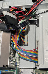
The new cable installed. I'm running the FDD off the HD power connector. I have already disabled the HD as it boots from a CF card now.

One question remains, and I'm not about to test it, is will this work without the XTIDE bios installed?
I've never attempted it. I have another T3200 in the garage I should pull out and check it over, I could test it on that. It's in pretty bad shape though, lots of rust on the back.

Reply 30 of 45, by Tiido

User metadata
Rank l33t
Rank
l33t

XTIDE did work when I last tried it, but that is still an ongoing project to give the thing a regular IDE port and hack the BIOS so it will not complain when the original HDD controller has gone missing 🤣

T-04YBSC, a new YMF71x based sound card & Official VOGONS thread about it
Newly made 4MB 60ns 30pin SIMMs ~
mida sa loed ? nagunii aru ei saa 😜

Reply 31 of 45, by steevf

User metadata
Rank Newbie
Rank
Newbie

The main problem I'm having with the XTIDE is in upgrading it's BIOS. I must have tried 15 different configurations as recommend from XTIDE Universal BIOS but none of them work. They all seem to "brick" the T3200 computer. I dumped the original XTIDE Universal BIOS from the XTIDE card when I bought it so I have had that to go back to and it does appear to work with that version.
I just can't get anything else to work. And one thing I never checked before I started using the XTIDE was the EMS memory. It doesn't appear to be accessible anymore with the XTIDE card installed and I wonder if it's because the EMS window overlaps the XTIDE BIOS ROM size. It's a massive 128K chip for some reason and the BIOS itself fits in 2K. I'm not really sure I understand how this is all working.

Reply 32 of 45, by Tiido

User metadata
Rank l33t
Rank
l33t

You definitely have an address conflict there, but without knowing the hardware you are using to change address and size of mapped area it is difficult to know what soluton can be.

I used XTIDE on a 3com card but I don't remember to what address I placed it, probably at $C8000...CFFFF range, I vaguely remember $D0000...DFFFF being EMS window. I also had the original HDD controller removed but I am not sure if it actually gets in the way or not. All I know is that the BIOS has a long timeout on the HDD controller detection where it appears to do nothing but eventually it tells that it cannot find it, and normal boot continued. One day I'll finish CF addon to the 3com card and then I'll hack the BIOS to get rid of the timeout but that day is not near, other things will take priority.

T-04YBSC, a new YMF71x based sound card & Official VOGONS thread about it
Newly made 4MB 60ns 30pin SIMMs ~
mida sa loed ? nagunii aru ei saa 😜

Reply 33 of 45, by steevf

User metadata
Rank Newbie
Rank
Newbie

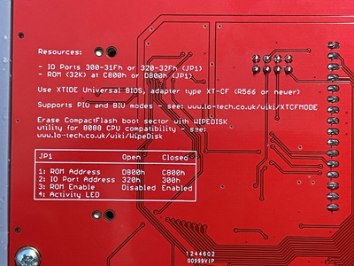
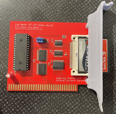
It says on the back of the XT-CF ISA card that it's currently set to C800h based on Jumper 1 being closed.

2023-06-18 20.58.01 rot small.jpg
Filename
2023-06-18 20.58.01 rot small.jpg
File size
529.37 KiB
Views
820 views
File license
CC-BY-4.0

I'm guessing that the ISA card isn't capable of putting all 20 address lines on it so I'm guessing that most of that ROM chip isn't reachable. I'll have to pull it out and look at it closer when I get the chance.

2023-06-18 19.12.34 crop.jpg
Filename
2023-06-18 19.12.34 crop.jpg
File size
885.93 KiB
Views
820 views
File license
CC-BY-4.0

Reply 34 of 45, by Tiido

User metadata
Rank l33t
Rank
l33t

Ok, this card exposes 32KB of the chip to outside world so C8000...CFFFF range is used in that jumper setting, which in theory shouldn't collide with anything. Top two address lines are grounded so the remaining 96KB are inaccessible entirely.

T-04YBSC, a new YMF71x based sound card & Official VOGONS thread about it
Newly made 4MB 60ns 30pin SIMMs ~
mida sa loed ? nagunii aru ei saa 😜

Reply 35 of 45, by steevf

User metadata
Rank Newbie
Rank
Newbie

I was figuring as much without actually looking at it closer. So something else had gone wrong with the EMS. Since I was using an old version of Norton Diagnostics to run the test, it also told me the register test of the FPU failed. I'm worried that I've accidentally drop a screw on the circuit board somewhere and it's still there.

Reply 36 of 45, by 16ShadesOfOrange

User metadata
Rank Newbie
Rank
Newbie

@steevf some great work here, I'll have to distill it and add it to my page.

My T3200 arrived, it's got the 1.44MB FDD (yay) but it's dead (boo). XT-IDE @300H works nicely, and even mounts as D:\ if you have a working C:\ drive!

I replaced the dead CMOS battery with 2x AAs - so far so good. I'm not man enough to try a 3.7v 18650, even though the voltage is only slightly higher than the stock 3.6v battery.

I also have lines down the screen which I'll take a look at but don't think I'll be able to fix.

Sadly no 3MB expansion card 🙁 I think I imagined someone asking somewhere for pics in the hope of building their own ? I found some pics online: https://imgur.com/a/d43Enrj

I'm still trying to boot the thing from another working floppy so I can SYS C: and utilise the working 40MB HDD (keep it original). Might add a sound card as well.

💻 Toshiba T5200 info
💻 Toshiba T3200SX info
💻 Toshiba T3200 info

Reply 37 of 45, by bocha

User metadata
Rank Newbie
Rank
Newbie

Sorry to interrupt, but I saw that topicstarter had his Toshiba with a VGA card. So, I have a T3200 with a dead display. I currently have nothing to connect it to an EGA. The monitors seem to be non-existent, like they never have, I don't get it, nobody sales even one. The converters from cga/ega to VGA do not remotly resemble what I actually need (I don't see an actual db9 port on any of them, so what even are they?). I saw a video describing a passive db9/db25 adapter that actually works if you have a 15kHz vga monitor, so I found one but it does not work. So I gave up on ega output and installed a VGA card inside. But it does not work either. As I understand I have to tune the BIOS to make "external" vga card work, but I dont have any output to do that. Yet I am sure the system works, it flashes keyboard leds, then checks the floppy drive and then starts to actively blink the "left drive" for some seconds and stops. I'm pretty sure its the DOS that boots up. Just no video. Maybe someone can tell me the sequence to press so I can enable ISA VGA blindly. There's a lot of BIOSes I can navigate blindly just because I remember how to get there and what to press to achieve this and that, so I don't need a monitor that much. Maybe it may work here too? That would be very apprectiated. Thanks. Any other options and advices would be nice too.

Reply 38 of 45, by Tiido

User metadata
Rank l33t
Rank
l33t

The displays are specific to T3200 and you only get another such display from another T3200, that is why nobody sells them. Your best bet is to find another T3200 and frankenstein a working one out of the two.

DB9 output is standard CGA/EGA output and you have to set DIP switches right to get right kind of output from it (there's a special 400 line Toshiba mode that requires a capable display, as there are 27kHz and 15kHz EGA modes). You can also use a VGA card etc. when the DIPs are set right, without, the original EGA chipset will get in the way and you will get nowhere. You can find DIPs from the manual of the machine and in the link in bottom of the post right above yours.

T3200 has no BIOS with user settings, you have to use machine specific conf utility from DOS etc. to change settings like on some other early PCs. There are Toshiba specific DOS installations floppies floating around that happen to have these utils along with EMS driver.

T-04YBSC, a new YMF71x based sound card & Official VOGONS thread about it
Newly made 4MB 60ns 30pin SIMMs ~
mida sa loed ? nagunii aru ei saa 😜

Reply 39 of 45, by bocha

User metadata
Rank Newbie
Rank
Newbie

Thanks, Tiido. I see.
So basically I can't set a VGA card without a working EGA output, because it is done through software, which I obviously have to see on the monitor to use, and I don't have one. When I said that nobody sells a EGA display, I didn't mean that plasma one, god forbid, I would not even try to look for it, I mean just a normal EGA display, just for me to see anything. I can't find any EGA display for sale in my region.

So, then, my best bet is to find a EGA to VGA converter, guess the DIP positions and change to VGA only after I get anything at all from anything at all. I mean, ofcourse I read an Owner's Manual, and I can't really understand what's so specific about this EGA output, just switching from 40 to 80 columns, but nothing fancy. And yet I can't actually undestand for sure that I don't have to make the port work at all, because I can't firgure out if manual tells me that the EGA DB9 port is on by default or not. My guess is that it is, and I must get at least something if I connect a generic EGA monitor to it. Am I wrong?