VOGONS


AT PSU voltage question

Topic actions

Reply 20 of 22, by newlsb00

User metadata
Rank Newbie
Rank
Newbie

Quick question for Horun (I couldn't figure out if there is some kind of pm function on this forum, so I will post publicly):
Do you happen to have a wiring diagram (or just a manual) for any of your HEC 250 PSUs? I can't find one online anywhere, at least through googling around, didn't know if you had or knew of an accessible copy. Looking at what I've got here, I'm not sure what is what (apart from the obvious main AXT connection - I'm assuming I need to connect more than just the MB via adapter). Thanks!

Reply 21 of 22, by Horun

User metadata
Rank l33t++
Rank
l33t++

I do not have the schematic to the HEC. Do you have a ATX PSU tester ? I have a cheap simple one similar to the pictured below.
That way I can test the output volts without using a motherboard, just an old scrappy HD. I use a DVM and actually measure the volts if all the LED turn on like they should.
You attach the ATX/AT adapter to the ATX PSU and then attach the P8 and P9 connectors on adapter to the mobo just like a regular AT supply. The switch leads need to go to a real on/off switch, not a momentary contact type. Most AT PSU have a external switch on a cable with 4 wires, you need a switch just like it but you only use two of those. As a temp solution to test it: you could just short those two leads together to turn it on, is a 5v low amp circuit not worry about sparks, electrocution, etc (NEVER do this with a real AT: always use a real switch!). Your HD's and floppies are connected to the PSU the same way as any PSU.
added: I would test the HEC before hooking it up to any mobo, being you bought it used it could have an issue not disclosed, they are very well built but still would test it if it were me. Volts should be with in 10% of the rated on all volts and be less than +/-5% values on the +5 and +12v for a good target.

Attachments

  • psu tester.jpg
    Filename
    psu tester.jpg
    File size
    65.31 KiB
    Views
    139 views
    File license
    Public domain

Hate posting a reply and then have to edit it because it made no sense 😁 First computer was an IBM 3270 workstation with CGA monitor. Stuff: https://archive.org/details/@horun

Reply 22 of 22, by newlsb00

User metadata
Rank Newbie
Rank
Newbie

One step forward...a leisurely jog backwards. Sorry for prolonging this, but I'm stuck anew at the PSU wiring. So, I did a voltage test on the "new" ATX, and everything looks swell (though I ended up getting a newer one that didn't have a -5v in the tester, but I'm not 100% sure my AT/ATX adapter even has a -5v, and I'm reasonable sure from reading around vogons that none of the equipment I have needs -5v anyway.)

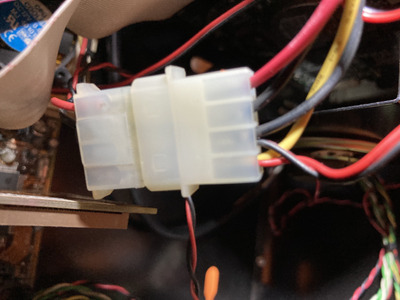
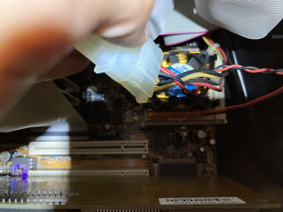
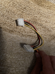
But in the old AT PSU, the HDD power wire comes down to a plastic 4pin m/f connector and then goes up to the HDD. That's fine, but in addition to the four main wires, there are a couple of thinner two wire split offs from each side of the connector that run to the separate CPU heatsink and the Mhz readout on the case. Photos attached. Basically they powered a couple other things from the HDD power line. But there is obviously nothing quite like this coming off the newer ATX, just a pair of 4 pin connections.

My main question is: am I going to have to rewire this if I want to power the heatsink / case readout with the ATX PSU? If yes - and this will show my vast inexperience here - is there an easy way to pry apart each of the plastic connectors (not the m/f from each other - that's easy, I mean open each of the plastic cases to expose the ends of the wires) so that I can just add the existing pair of offshoots into the (opened) ATX plastic sleeve, basically just mirroring what is in there now? Well, it wouldn't be exactly the same, since I would have to run BOTH pairs into a single 4 pin (which maybe wouldn't work?). Or would I have to cut the wires at the plastic and redo the whole connection?

Hope this is relatively clear - I'm sure there are names for things that I'm getting wrong. First two photos are from the AT, the third is from the ATX (though I'm sure that one is familiar to everyone on here already.)

Attachments

  • IMG_1127.JPG
    Filename
    IMG_1127.JPG
    File size
    1.78 MiB
    Views
    115 views
    File license
    Public domain
  • IMG_1359.JPG
    Filename
    IMG_1359.JPG
    File size
    1.8 MiB
    Views
    115 views
    File license
    Public domain
  • IMG_0119 3.JPG
    Filename
    IMG_0119 3.JPG
    File size
    1.47 MiB
    Views
    115 views
    File license
    Public domain