First post, by Soyburger
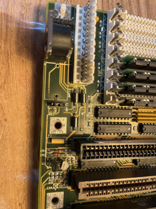
Hello, I recently purchased a BC3486UL motherboard from eBay that had a corroding battery. Needless to say I’ve cleaned it all up. The motherboard works great and I’m trying to connect an external battery to the external battery header.
I got the specs from stason.org but the manufacturer is unidentified and it doesn’t have the pinout of the external battery header.
Does anyone know the pinout or what voltage battery I should use. It has 4 pins and pins 2 and 3 were jumpered to use the internal battery
I’m not married to any solution I can do normal AA’s at 3, 4.5 or 6 volts, I can do a 3.6v (that’s what the soldered battery was) I can do 3v coin cell.
Any help would be great, I don’t want to do trial and error and blow something up.
Thanks for any help.