VOGONS


Help fixing my Aptiva's pc speaker

Topic actions

First post, by DoutorHouse

User metadata
Rank Newbie
Rank
Newbie

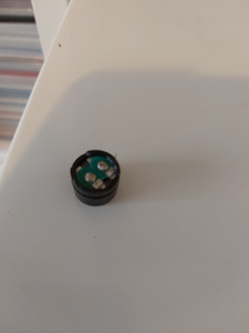
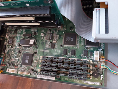
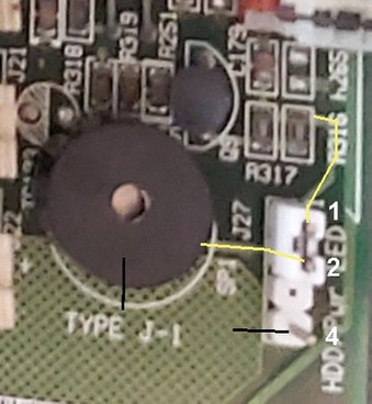
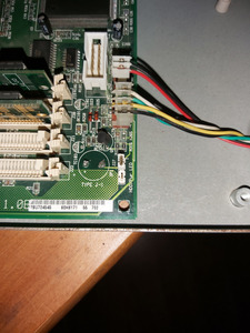
So, while installing new RAM on my IBM Aptiva, I accidentally pushed the pc speaker on the side of the motherboard and it fell out of place... I tried to move it back in place but it was soldered to the motherboard and it completely came out... Was thinking of getting another one but my motherboard doesn't have any place to connect one (with 4 pins), just a 2 pin jumper to enable/disable the soldered speaker...

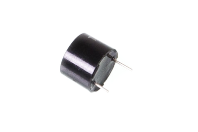
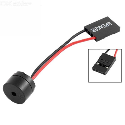
Is it wise to ask someone to try to solder it back into place? I have another one with two wires (red and black, exactly like the one in the picture) and that would be probably easier to solder back into the motherboard but then where would i place the speaker? It's magnetic and i don't want to damage the motherboard even further...

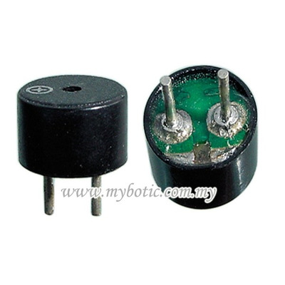
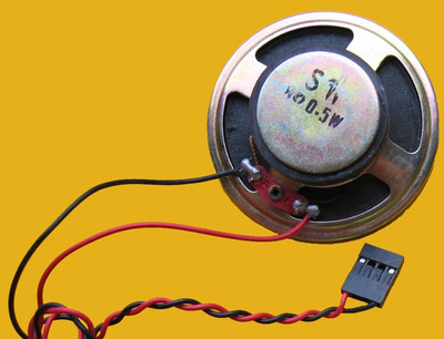
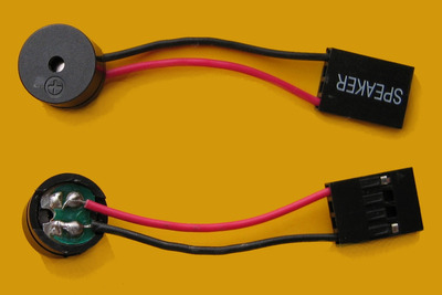
My speaker looks like this one... except it does not have the wires, because it was soldered into the motherboard:

PC-Speaker_IMG_9311-9312.JPG
Filename
PC-Speaker_IMG_9311-9312.JPG
File size
112.86 KiB
Views
784 views
File license
Fair use/fair dealing exception

Any help is appreciated!! Thanks!

Reply 1 of 23, by Horun

User metadata
Rank l33t++
Rank
l33t++

Most of those onboard PC speakers are Coil+Magnet but a rare few are PIZO speakers. If the original is a Coil+Magnet then yes you could solder the one you have onto the board using short solid core wire which does not bend as easily. You may have to remove the board from the case to do it properly but a good picture of that area will tell us if that is needed.

Hate posting a reply and then have to edit it because it made no sense 😁 First computer was an IBM 3270 workstation with CGA monitor. Stuff: https://archive.org/details/@horun

Reply 2 of 23, by DoutorHouse

User metadata
Rank Newbie
Rank
Newbie
Horun wrote on 2020-08-21, 01:11:

Most of those onboard PC speakers are Coil+Magnet but a rare few are PIZO speakers. If the original is a Coil+Magnet then yes you could solder the one you have onto the board using short solid core wire which does not bend as easily. You may have to remove the board from the case to do it properly but a good picture of that area will tell us if that is needed.

Thank you so much for replying! I noticed the speaker was magnetic right before it fell off the motherboard... Now it doesn't seem to attach itself to metal, so i'm not 100% sure... Is it a piezo or a coil+magnet one?

At this site, the guy reviewing an IBM Aptiva (almost same model as mine), says it has a piezo speaker:

https://ancientelectronics.wordpress.com/tag/ … iva-model-2176/

This is what my motherboard looks like. You can see the speaker on the right low corner, and the jumper to enable it right next to it. Picture was taken before the speaker was damaged:

20200820_163614.jpg
Filename
20200820_163614.jpg
File size
917.24 KiB
Views
748 views
File license
Fair use/fair dealing exception
20200424_182602.jpg
Filename
20200424_182602.jpg
File size
1.59 MiB
Views
748 views
File license
Fair use/fair dealing exception

A scheme for my motherboard is here:
https://www.infania.net/misc/eprmhtml/eprm/f284.html

I also noticed that J27 "could" allow to connect a 4-pin connector... Maybe i could connect a different pc speaker to this connector or would it damage the motherboard?

Last edited by DoutorHouse on 2020-08-21, 09:56. Edited 1 time in total.

Reply 4 of 23, by DoutorHouse

User metadata
Rank Newbie
Rank
Newbie
Doornkaat wrote on 2020-08-21, 09:40:

I'd just solder two wires to the speaker and connect them to the motherboard. It won't sit flush like that but you're less likely to knock it off again that way. 😉

Thanks. But where should i put the speaker then? Sitting on the motherboard somewhere or inside the case somewhere? If it's indeed magnetic, should it attach inside?

Reply 5 of 23, by Doornkaat

User metadata
Rank l33t
Rank
l33t

If this uses a magnet I doubt it's strong enough to stick it to the case.
I'd use short cables and leave it dangling around or use hot glue to attach it to the motherboard. Or maybe just zip tie it to the holein the corner.

Reply 6 of 23, by kalohimal

User metadata
Rank Member
Rank
Member

It's quite easy to identify piezo buzzer vs magnetic speaker. The buzzer has a plastic sealed bottom while the speaker doesn't.

Piezo buzzer:

Piezo.png
Filename
Piezo.png
File size
29.33 KiB
Views
721 views
File license
Fair use/fair dealing exception

Speaker:

speaker.jpg
Filename
speaker.jpg
File size
36.77 KiB
Views
721 views
File license
Fair use/fair dealing exception

Usually those that are soldered onto the motherboard are with 2 legs (like the one above), while those with wires have 2 solder pads. If you want it to flush with the motherboard then get a proper replacement, desolder the 2 broken legs on the motherboard, and solder the new one in. Otherwise if you have the 2 wires type, it would be fine to solder the wires on to the motherboard. It's ok to leave it dangling. I would normally use hot glue to seal up it's bottom to prevent short circuit, you could do the same, plus glue it onto the board. Of course the neatest would be to replace with a new 2 legged one.

Slow down your CPU with CPUSPD for DOS retro gaming.

Reply 7 of 23, by DoutorHouse

User metadata
Rank Newbie
Rank
Newbie
kalohimal wrote on 2020-08-21, 11:07:
It's quite easy to identify piezo buzzer vs magnetic speaker. The buzzer has a plastic sealed bottom while the speaker doesn't. […]
Show full quote

It's quite easy to identify piezo buzzer vs magnetic speaker. The buzzer has a plastic sealed bottom while the speaker doesn't.

Piezo buzzer:
Piezo.png

Speaker:
speaker.jpg

Usually those that are soldered onto the motherboard are with 2 legs (like the one above), while those with wires have 2 solder pads. If you want it to flush with the motherboard then get a proper replacement, desolder the 2 broken legs on the motherboard, and solder the new one in. Otherwise if you have the 2 wires type, it would be fine to solder the wires on to the motherboard. It's ok to leave it dangling. I would normally use hot glue to seal up it's bottom to prevent short circuit, you could do the same, plus glue it onto the board. Of course the neatest would be to replace with a new 2 legged one.

Thanks for all the info! I guess mine is not a piezo, afterall!
I grabbed a different speaker from another computer (this one has a 4 pin connector and now i'm tempted to plug it into the J27 jumper on my motherboard to see if it works... Would it damage the motherboard if it doesn't work?

Reply 8 of 23, by kalohimal

User metadata
Rank Member
Rank
Member

Jumper J27 does look like a 4 pin speaker header. Usually it has only 2 pins at the side with the center 2 pins removed. For you case, if like what you said the jumper is for enabling/disabling the on board speaker, then yes it is safe to just remove the jumper and plug in the 2 wires speaker you shown in your first post into J27, so no soldering is needed.

Slow down your CPU with CPUSPD for DOS retro gaming.

Reply 9 of 23, by DoutorHouse

User metadata
Rank Newbie
Rank
Newbie
kalohimal wrote on 2020-08-21, 11:38:

Jumper J27 does look like a 4 pin speaker header. Usually it has only 2 pins at the side with the center 2 pins removed. For you case, if like what you said the jumper is for enabling/disabling the on board speaker, then yes it is safe to just remove the jumper and plug in the 2 wires speaker you shown in your first post into J27, so no soldering is needed.

Yeah, i plugged a regular speaker into that jumper27 and nothing happened... There's no sound.... Motherboard is still ok, though.

Reply 10 of 23, by kalohimal

User metadata
Rank Member
Rank
Member

Hmm maybe It is pin 2 that is the signal pin. If you have a multimeter you could check to see which pin connects to the broken pin of the original speaker. Alternatively, you could take the receptacles out from the 4 holes plastic shell, and connect them to the header naked. Try pin 1 and pin 4 of the header, or pin 2 and pin 4 (which most likely is Vcc).

Slow down your CPU with CPUSPD for DOS retro gaming.

Reply 11 of 23, by DoutorHouse

User metadata
Rank Newbie
Rank
Newbie
kalohimal wrote on 2020-08-21, 13:25:

Hmm maybe It is pin 2 that is the signal pin. If you have a multimeter you could check to see which pin connects to the broken pin of the original speaker. Alternatively, you could take the receptacles out from the 4 holes plastic shell, and connect them to the header naked. Try pin 1 and pin 4 of the header, or pin 2 and pin 4 (which most likely is Vcc).

Well, the Jumper27 only has 3 pins (one is apparently missing). For the motherboard speaker to work, pins 1 and 2 must be shorted. I tried using just some wires against the place where the speaker used to be but it didn't work at all (probably bad contact, maybe it would work if it was soldered). I don't have a multimeter, though, but your suggestion seems pretty good. Was expecting this speaker would work when connected to the Jumper27 but maybe it's not designed for that or it's still assuming the other speaker is still in place (maybe because it was broken and its contacts are still on the motherboard?)...

Speaker i tried to connect to that weird J27 location is exactly like this one:

PC-Speaker_IMG_8161_(cropped).JPG
Filename
PC-Speaker_IMG_8161_(cropped).JPG
File size
107.01 KiB
Views
681 views
File license
Fair use/fair dealing exception

This is my System Board Layout:

System Board Layout - Type A-1.JPG
Filename
System Board Layout - Type A-1.JPG
File size
35.35 KiB
Views
681 views
File license
Fair use/fair dealing exception

So, maybe i should try connecting the red wire to pin 1 and the black wire to pin 4? If it doesn't work, try the red wire on pin 2 and the black one on pin 4? Maybe i'm confusing the wire colours? Thanks again for all the help!

Reply 12 of 23, by kalohimal

User metadata
Rank Member
Rank
Member
DoutorHouse wrote on 2020-08-21, 17:04:

So, maybe i should try connecting the red wire to pin 1 and the black wire to pin 4? If it doesn't work, try the red wire on pin 2 and the black one on pin 4? Maybe i'm confusing the wire colours? Thanks again for all the help!

Yup try this. The color doesn't matter, if the polarity is reversed the speaker cone will just move in the reverse direction. You'll still get the sound.

Slow down your CPU with CPUSPD for DOS retro gaming.

Reply 13 of 23, by DoutorHouse

User metadata
Rank Newbie
Rank
Newbie
kalohimal wrote on 2020-08-21, 17:20:
DoutorHouse wrote on 2020-08-21, 17:04:

So, maybe i should try connecting the red wire to pin 1 and the black wire to pin 4? If it doesn't work, try the red wire on pin 2 and the black one on pin 4? Maybe i'm confusing the wire colours? Thanks again for all the help!

Yup try this. The color doesn't matter, if the polarity is reversed the speaker cone will just move in the reverse direction. You'll still get the sound.

Still no sound... 🙁 I got another speaker like the one on the picture above and managed to break the connector into two, so i could plug the wires into all different pins, and still no luck. Maybe that Jumper27 isn't designed to connect a pc speaker or maybe the motherboard somehow still thinks the old speaker is still attached to it? I'm tempted to try to remove the soldered bits but i'm not even sure if the motherboard is supposed to have two "holes" in it to fit a new speaker or not...

PC Speaker.jpg
Filename
PC Speaker.jpg
File size
26.39 KiB
Views
659 views
File license
Fair use/fair dealing exception

Reply 14 of 23, by Horun

User metadata
Rank l33t++
Rank
l33t++
DoutorHouse wrote on 2020-08-21, 08:43:

Thank you so much for replying! I noticed the speaker was magnetic right before it fell off the motherboard... Now it doesn't seem to attach itself to metal, so i'm not 100% sure... Is it a piezo or a coil+magnet one?

At this site, the guy reviewing an IBM Aptiva (almost same model as mine), says it has a piezo speaker:

https://ancientelectronics.wordpress.com/tag/ … iva-model-2176/

If it was a Piezo then you have to replace with a Piezo, the mag+coil speaker will have too little impedance (1k ohm piezo versus 8 ohm typical for mag+coil).
many cheap headphones use a 32 ohm speaker which might work since the impedance is higher, I say "might work"...

Hate posting a reply and then have to edit it because it made no sense 😁 First computer was an IBM 3270 workstation with CGA monitor. Stuff: https://archive.org/details/@horun

Reply 15 of 23, by DoutorHouse

User metadata
Rank Newbie
Rank
Newbie
Horun wrote on 2020-08-22, 15:43:
DoutorHouse wrote on 2020-08-21, 08:43:

Thank you so much for replying! I noticed the speaker was magnetic right before it fell off the motherboard... Now it doesn't seem to attach itself to metal, so i'm not 100% sure... Is it a piezo or a coil+magnet one?

At this site, the guy reviewing an IBM Aptiva (almost same model as mine), says it has a piezo speaker:

https://ancientelectronics.wordpress.com/tag/ … iva-model-2176/

If it was a Piezo then you have to replace with a Piezo, the mag+coil speaker will have too little impedance (1k ohm piezo versus 8 ohm typical for mag+coil).
many cheap headphones use a 32 ohm speaker which might work since the impedance is higher, I say "might work"...

Thanks. I asked a friend to solder some wires to the original speaker and connected it to another pc and it was working fine. Then i soldered the two ends to my motherboard but i still get no sound at all... I'm still thinking maybe i could plug it to that j27 jumper, probably by removing one of the 3 pins, but i'm afraid that would ruin the motherboard... My last option is to completely remove the solder from the motherboard and solder it back again...

Reply 16 of 23, by Horun

User metadata
Rank l33t++
Rank
l33t++

Did you put the jumper back on J27 pin 1-2 ? From your picture I drew the on board signal lines, yellow and black. Yellow for SP and the black for Gnd or +5 (not sure which, but assume it is +5). You should be able to hook the original piezo to 1 and 4 of J27. Did you get a picture of that area with the piezo removed ?

Attachments

Hate posting a reply and then have to edit it because it made no sense 😁 First computer was an IBM 3270 workstation with CGA monitor. Stuff: https://archive.org/details/@horun

Reply 17 of 23, by DoutorHouse

User metadata
Rank Newbie
Rank
Newbie
Horun wrote on 2020-08-23, 22:35:

Did you put the jumper back on J27 pin 1-2 ? From your picture I drew the on board signal lines, yellow and black. Yellow for SP and the black for Gnd or +5 (not sure which, but assume it is +5). You should be able to hook the original piezo to 1 and 4 of J27. Did you get a picture of that area with the piezo removed ?

Yeah, i put the jumper back on J27 pins 1 and 2 but no still no sound. Then i tried all three speakers i own (the original now soldered and 2 others) on every combination of pins and still no luck. Maybe breaking or desoldering one of the pins will do the trick? Problem is that i'm not sure this jumper is even designed to connect a speaker this way, since it controls the one attached to the motherboard. Sorry for my lack of technical knowledge, this problem is really annoying me now. I can't find any more info on this specific motherboard and the manual isn't very helpful...

20200823_234756.jpg
Filename
20200823_234756.jpg
File size
1.6 MiB
Views
612 views
File license
Fair use/fair dealing exception

Reply 18 of 23, by Horun

User metadata
Rank l33t++
Rank
l33t++

Ok so the left on-board speaker solder pad (in your new picture) goes somewhere, can you use a DVM and check the ohms from it to both the +5 Red and Ground Black at the PSU connector (with power off of course ;p) ?
Then do same from Pin 4 on J27. That way we might be able to figure out a bit more w/o removing the motherboard....

Hate posting a reply and then have to edit it because it made no sense 😁 First computer was an IBM 3270 workstation with CGA monitor. Stuff: https://archive.org/details/@horun

Reply 19 of 23, by DoutorHouse

User metadata
Rank Newbie
Rank
Newbie
Horun wrote on 2020-08-23, 23:05:

Ok so the left on-board speaker solder pad (in your new picture) goes somewhere, can you use a DVM and check the ohms from it to both the +5 Red and Ground Black at the PSU connector (with power off of course ;p) ?
Then do same from Pin 4 on J27. That way we might be able to figure out a bit more w/o removing the motherboard....

Thanks. I'll have to ask my friend to do that, as i don't have a DVM. Couple of minutes ago i was so frustrated, i was tempted to break one of those pins and try to connect the speaker to the two remaining but i'm beginning to doubt i would accomplish anything, except damaging my computer. Was gonna break pin 1 and then connect a speaker to 2 and 4... but, with my luck, it's probably 1 and 4, or this j27 jumper won't even work... 😀