VOGONS


First post, by Xardion

User metadata
Rank Newbie
Rank
Newbie

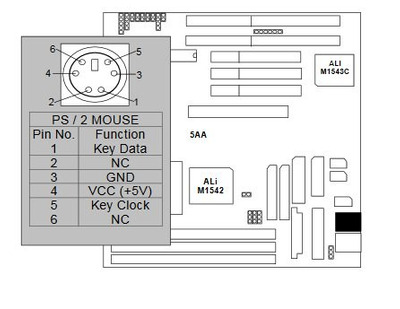
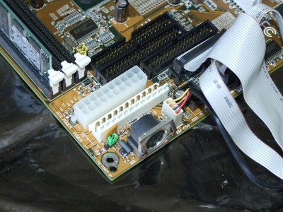
I purchased my GA-5AA second-hand, so I don't have the original PS/2 bracket, and I'm struggling to figure out the pinout, as the manual is useless in this regard, and I don't have a scope to figure it out with. If anyone knows the pinout, or has an original bracket for this board they can post pictures of, I'd greatly appreciate it.

Reply 1 of 5, by Horun

User metadata
Rank l33t++
Rank
l33t++

Do you have a good Digital Voltmeter ? Since it is a 4 pin connector One is Ground, One is +5. Once you figure those out it becomes easy: the two left are Data and Clock which would connect to the other two signal wires (some ps2 adapters have 6 wires but 2 are NC). If it does not work one way it should work swapped. Using any PS2 bracket and the proper 4 wires you should be able to get it to work.

Attachments

  • ps2 Giga.jpg
    Filename
    ps2 Giga.jpg
    File size
    25.24 KiB
    Views
    416 views
    File license
    Public domain

Hate posting a reply and then have to edit it because it made no sense 😁 First computer was an IBM 3270 workstation with CGA monitor. Stuff: https://archive.org/details/@horun

Reply 2 of 5, by Xardion

User metadata
Rank Newbie
Rank
Newbie

I only have an old analog multimeter, which works fine for most things, but I was reading 5v on more than one pin, probably the clock and +5v. I don't have a spare ps/2 mouse floating around at the moment, so I didn't want to find out if throwing +5v on the clock or data pin would kill the thing.

Reply 4 of 5, by Thermalwrong

User metadata
Rank Oldbie
Rank
Oldbie

Zoom in on the first picture here: http://retro-pc.ucoz.ru/index/gigabyte_ga_5aa/0-989

1. red
2. black
3. white?
4. yellow?

The manual for other gigabyte AT boards has the pinout listed, which matches up, see page 3-3: https://mbmanuals.retropc.se/manuals/47/586atv4.pdf

Here's another close-up of a different revision, but you can work out what's what because the connector is keyed:

gigabyte-ps2connector.jpg
Filename
gigabyte-ps2connector.jpg
File size
143.09 KiB
Views
361 views
File license
CC-BY-4.0

Reply 5 of 5, by Xardion

User metadata
Rank Newbie
Rank
Newbie
Thermalwrong wrote on 2020-09-11, 20:20:

The manual for other gigabyte AT boards has the pinout listed, which matches up, see page 3-3: https://mbmanuals.retropc.se/manuals/47/586atv4.pdf

Here's another close-up of a different revision, but you can work out what's what because the connector is keyed:

Oh, thanks for that! Didn't know about other Gigabyte AT boards having the same pinout, but I should have guessed. That pinout matches what I worked out from the pics I found. The pic you posted matches the board revision I have (v1.1), but the 2.2 and 3.2 boards are exactly the same, the connector is just turned 90 degrees.