VOGONS


First post, by Skip94

User metadata
Rank Newbie
Rank
Newbie

Hi all, fairly new here, but recently got back into tinkering with old PC's after a bit of a break. A friend of mine gave me one of his old computers, that he still had sat in the loft. Its a Pentium 166 system, came to me with 40MB of RAM, originally 8MB. 1.2GB Seagate drive with a really messy install of W95 on it.
I've done a bit of work on it, upgraded it to 64MB of RAM, changed out the original Cirrus Logic video card for a Matrox Mystique I had laying about and also added a sound, USB and Ethernet. Then did a fresh install of W95 onto a 4GB CF card.
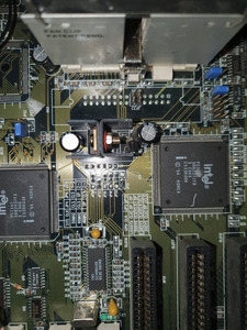
One thing I did rather want to do is to swap out the CPU for a Pentium 200MMX. The Motherboard is a labelled as a P5I437P4/FMB, which also seems to have been called a 430FXFMB. Seems to have been made by QDI, but it doesn't seem to be too common a board.
It seems to have been released before the MMX range of Pentium CPU's, but does have a pair of jumpers to drop the core voltage from 3.3V to 2.5V that I believe the earliest MMX CPU's ran at. It also has jumper settings to set the frequency anywhere up to 200MHz.
So... I bought a 200MMX CPU on ebay, as I've read online that a lot of these later 2.8V processors will run just fine at a lower voltage and sure enough it does seemingly fine. However, if I set the jumpers for 200MHz, the bios and CPUZ both report it running at 166MHz. I initially assumed this was just a fault with the board, but if I put the original 166 non MMX back in, I can happily clock that up to 200MHz, no issues.
Same thing happens with a 233MMX I also have, so I don't think its a CPU issue.
Is this a known issue with trying to run a later MMX CPU in an early board, or is there a known workaround?
Cheers
Andrew

Reply 1 of 18, by foil_fresh

User metadata
Rank Member
Rank
Member

take a photo of the cpu markings and the jumpers for fsb and multi if you can. possibly a fake/mobile chip? rare, but anythings possible.

https://www.elhvb.com/mobokive/archive/Qdi%20 … ls/430fxfmb.pdf i'll guess you're using this for the jumpers?

one more thing, does the 233mmx run at 166 or 200? it looks like the fastest the board will go is 3x66 for 200mhz.

Reply 2 of 18, by rmay635703

User metadata
Rank Oldbie
Rank
Oldbie

This is a common but very old issue
A single rail motherboard (one that does not have separate VIO/Vcore)
Lacks the ability to properly set jumpers causing them to float on split rail CPUs)
To set a jumper you need to be able to bring the multiplier pins high or to ground,

To fix you will need to run cheater wires to set the multiplier pins manually

(Oddly this issue seems to be quite common lately, there is recent thread with a process and the cpu socket pinout somewhere)

Mentioned later in this thread

Put a Pentium MMX 233mhz CPU in my DOS machine, still reads as Pentium-S 120mhz. What am I missing?

Reply 3 of 18, by Skip94

User metadata
Rank Newbie
Rank
Newbie
rmay635703 wrote on 2020-11-16, 10:31:
This is a common but very old issue A single rail motherboard (one that does not have separate VIO/Vcore) Lacks the ability to […]
Show full quote

This is a common but very old issue
A single rail motherboard (one that does not have separate VIO/Vcore)
Lacks the ability to properly set jumpers causing them to float on split rail CPUs)
To set a jumper you need to be able to bring the multiplier pins high or to ground,

To fix you will need to run cheater wires to set the multiplier pins manually

(Oddly this issue seems to be quite common lately, there is recent thread with a process and the cpu socket pinout somewhere)

Mentioned later in this thread

Put a Pentium MMX 233mhz CPU in my DOS machine, still reads as Pentium-S 120mhz. What am I missing?

I think you've got it!
I'd done quite a bit of googling on the subject, but failed to come up with anything. However another search for the multiplier pins turned up this site
https://vobarian.com/8500tvx.html
Which explains it quite well I feel.
I'm now off to find a 1k resistor and a couple of Dupont leads to test it out!
Really appreciate your help.
Cheers
Andrew

Reply 4 of 18, by Skip94

User metadata
Rank Newbie
Rank
Newbie

Well, that was unsuccessful... I made up a lead with a 1K resistor in, but as soon as JP2, which seems to be connected to BF0 on the processor, is pulled high, it refuses to post...
More head scratching required.
Andrew

Reply 5 of 18, by rmay635703

User metadata
Rank Oldbie
Rank
Oldbie
Skip94 wrote on 2020-11-16, 18:42:

Well, that was unsuccessful... I made up a lead with a 1K resistor in, but as soon as JP2, which seems to be connected to BF0 on the processor, is pulled high, it refuses to post...
More head scratching required.
Andrew

Make sure your jumper setting isn’t trying to ground the pin, mike need to remove the cpu fire up use a multimeter and see what is going on

Reply 6 of 18, by Skip94

User metadata
Rank Newbie
Rank
Newbie

I've had a poke around with a multimeter and now I'm completely confused as to why it won't work. This is what I've found.
Pin BF0 on the CPU is connected to one of the pins of jumper 2 - 0Ω. The other side of JP2 is connected to ground - 100Ω
With a non MMX Pentium in there and no jumper fitted at JP2 then the BF0 pin is a 3.3V. This is obviously the internal pull up resistor making it high.
With an MMX Pentium and no jumper, that pin is at 0V
With an MMX Pentium and my lead with the 1K resistor to pull it high, it sits at 3.3v, and will not POST.
With a non MMX Pentium and my lead with the 1K resistor to pull it high, it sits at 3.3v, and works just fine.
With no processor fitted and no jumper, the is no connection to BF0/then non ground side of JP2 at all
I'm going to have to either accept that its going to stay at 166mhz or do some more investigation!
Andrew

Reply 7 of 18, by SSTV2

User metadata
Rank Oldbie
Rank
Oldbie
Skip94 wrote on 2020-11-17, 16:54:
I've had a poke around with a multimeter and now I'm completely confused as to why it won't work. This is what I've found. Pin B […]
Show full quote

I've had a poke around with a multimeter and now I'm completely confused as to why it won't work. This is what I've found.
Pin BF0 on the CPU is connected to one of the pins of jumper 2 - 0Ω. The other side of JP2 is connected to ground - 100Ω
With a non MMX Pentium in there and no jumper fitted at JP2 then the BF0 pin is a 3.3V. This is obviously the internal pull up resistor making it high.
With an MMX Pentium and no jumper, that pin is at 0V
With an MMX Pentium and my lead with the 1K resistor to pull it high, it sits at 3.3v, and will not POST.
With a non MMX Pentium and my lead with the 1K resistor to pull it high, it sits at 3.3v, and works just fine.
With no processor fitted and no jumper, the is no connection to BF0/then non ground side of JP2 at all
I'm going to have to either accept that its going to stay at 166mhz or do some more investigation!
Andrew

Your observations make complete sense as MMX Pentiums have BF0 pin pulled-down and BF1 pulled-up internally by default on all models (or CPU DIEs to be exact). Your non-POST issue with a MMX CPU set to 200MHz most likely is caused by insufficient power delivery, P55C is guaranteed to operate at rated frequency only when the core voltage is set between 2.7 and 2.9V. Some CPUs might operate well at rated freq. and at below intended core voltage, but in your case, it obviously doesn't.

Set core voltage to 3.3V (it won't damage CPU even in the long run) and connect BF0 directly or through a pull-up resistor to Vcc I/O.

PS. you can easily modify linear power regulator to output 2.8V instead of 2.5V by replacing resitor(s) responsible for setting Vref voltage.

Reply 8 of 18, by Skip94

User metadata
Rank Newbie
Rank
Newbie
SSTV2 wrote on 2020-11-17, 23:22:
Your observations make complete sense as MMX Pentiums have BF0 pin pulled-down and BF1 pulled-up internally by default on all mo […]
Show full quote
Skip94 wrote on 2020-11-17, 16:54:
I've had a poke around with a multimeter and now I'm completely confused as to why it won't work. This is what I've found. Pin B […]
Show full quote

I've had a poke around with a multimeter and now I'm completely confused as to why it won't work. This is what I've found.
Pin BF0 on the CPU is connected to one of the pins of jumper 2 - 0Ω. The other side of JP2 is connected to ground - 100Ω
With a non MMX Pentium in there and no jumper fitted at JP2 then the BF0 pin is a 3.3V. This is obviously the internal pull up resistor making it high.
With an MMX Pentium and no jumper, that pin is at 0V
With an MMX Pentium and my lead with the 1K resistor to pull it high, it sits at 3.3v, and will not POST.
With a non MMX Pentium and my lead with the 1K resistor to pull it high, it sits at 3.3v, and works just fine.
With no processor fitted and no jumper, the is no connection to BF0/then non ground side of JP2 at all
I'm going to have to either accept that its going to stay at 166mhz or do some more investigation!
Andrew

Your observations make complete sense as MMX Pentiums have BF0 pin pulled-down and BF1 pulled-up internally by default on all models (or CPU DIEs to be exact). Your non-POST issue with a MMX CPU set to 200MHz most likely is caused by insufficient power delivery, P55C is guaranteed to operate at rated frequency only when the core voltage is set between 2.7 and 2.9V. Some CPUs might operate well at rated freq. and at below intended core voltage, but in your case, it obviously doesn't.

Set core voltage to 3.3V (it won't damage CPU even in the long run) and connect BF0 directly or through a pull-up resistor to Vcc I/O.

PS. you can easily modify linear power regulator to output 2.8V instead of 2.5V by replacing resitor(s) responsible for setting Vref voltage.

Thanks.
Sadly that doesn't appear to be the case. Setting it to 3.3v still gives no post. Not damaging the processor though, as once set back to 166MHz it works just fine.
I have to pull the board out in the next couple of days as, despite it being original to the case, its a horrible fit on the motherboard tray. Only 1 screw going into a proper stand off, the rest being nasty plastic clips that fall out and allow it to flop around. It also sits too low so the PCI/ISA cards are barely going into the slots. I've ordered a sheet of black plastic and some short standoffs to build effectively an adaptor plate.
I was going to look at adapting it to 2.8V as well while it was out, it seems to use a 2nd voltage regulator chip, so I'm hoping I can just desolder it and swap in a 2.8V one.
A little more head scratching required!
Cheers
Andrew

Reply 9 of 18, by dionb

User metadata
Rank l33t++
Rank
l33t++
SSTV2 wrote on 2020-11-17, 23:22:

[...]

PS. you can easily modify linear power regulator to output 2.8V instead of 2.5V by replacing resitor(s) responsible for setting Vref voltage.

It will even make it more efficient 😉

Skip94 wrote on 2020-11-18, 15:05:
[...] […]
Show full quote

[...]

Thanks.
Sadly that doesn't appear to be the case. Setting it to 3.3v still gives no post. Not damaging the processor though, as once set back to 166MHz it works just fine.
I have to pull the board out in the next couple of days as, despite it being original to the case, its a horrible fit on the motherboard tray. Only 1 screw going into a proper stand off, the rest being nasty plastic clips that fall out and allow it to flop around. It also sits too low so the PCI/ISA cards are barely going into the slots. I've ordered a sheet of black plastic and some short standoffs to build effectively an adaptor plate.
I was going to look at adapting it to 2.8V as well while it was out, it seems to use a 2nd voltage regulator chip, so I'm hoping I can just desolder it and swap in a 2.8V one.

The voltage regulator almost certainly isn't fixed to 2.5V, it just has a reference input determined by a resistor between Vio and the VRM. Put a smaller resistor on there and you get a higher voltage. Exactly which resistor and which voltage depends on the VRM model. If you could share it with us we can look up what's happening and what value you need for 2.8V.

Reply 10 of 18, by SSTV2

User metadata
Rank Oldbie
Rank
Oldbie

Wow, now that's odd. I have three possible explanations why your MB still doesn't POST when P55C is set to 200MHz.

1. Power delivery is still not sufficient, measure Vcc core as close as possible to the socket when MMX CPU is installed and voltage is set as single rail, perhaps it drops under load? If you get volage drop, put tightest jumpers you have on headers where VRM connector is supposed to be.
2. Some bizarre BIOS bug. During POST, BIOS identifies CPU type and calculates/looks up for its frequency and perhaps it halts, because BIOS cannot identify such CPU's freq. and type combo?
3. Very used CPU or some fake.

You should use 7mm~ female-female standoffs instead of making an adaptor on a plate, just screw standoffs on motherboard, adjust its position in the case and screw other side of standoffs to the MB holding plate. No need to replace voltage regulator IC as dionb mentioned, its output can be adjusted.

Reply 11 of 18, by Skip94

User metadata
Rank Newbie
Rank
Newbie
dionb wrote on 2020-11-18, 15:23:

The voltage regulator almost certainly isn't fixed to 2.5V, it just has a reference input determined by a resistor between Vio and the VRM. Put a smaller resistor on there and you get a higher voltage. Exactly which resistor and which voltage depends on the VRM model. If you could share it with us we can look up what's happening and what value you need for 2.8V.

I pulled the board and had a closer look. What I assumed was going to be a integrated VRM is just a large Darlington transistor. My electronics knowledge is a little hazy, so apologies of I sound like I don't quite know what I'm doing!
I'll attach a pic of that area of the board. There are a few surface mount resistors in that area, not the sort that I'd feel comfortable desoldering and swapping out myself though. However, there also a bank of wire jumpers, so I'm wondering if they may have something to do with it. If needs be, I'll pull the board out again and do some visual tracing. All of the wires measure different resistances to ground, mostly in the 1k-10K ohms range.

Cheers
Andrew

Attachments

Reply 12 of 18, by Skip94

User metadata
Rank Newbie
Rank
Newbie
SSTV2 wrote on 2020-11-18, 18:02:
Wow, now that's odd. I have three possible explanations why your MB still doesn't POST when P55C is set to 200MHz. […]
Show full quote

Wow, now that's odd. I have three possible explanations why your MB still doesn't POST when P55C is set to 200MHz.

1. Power delivery is still not sufficient, measure Vcc core as close as possible to the socket when MMX CPU is installed and voltage is set as single rail, perhaps it drops under load? If you get volage drop, put tightest jumpers you have on headers where VRM connector is supposed to be.
2. Some bizarre BIOS bug. During POST, BIOS identifies CPU type and calculates/looks up for its frequency and perhaps it halts, because BIOS cannot identify such CPU's freq. and type combo?
3. Very used CPU or some fake.

You should use 7mm~ female-female standoffs instead of making an adaptor on a plate, just screw standoffs on motherboard, adjust its position in the case and screw other side of standoffs to the MB holding plate. No need to replace voltage regulator IC as dionb mentioned, its output can be adjusted.

Very odd!
I'll stick a multimeter directly on the CPU later, see what voltage I'm getting there. Fairly confident its not that though.
I'm starting to get the feeling that it may be a BIOS bug and I'll just have to live with it. Flashing BIOSs is something I've always been very nervous about doing, plus I don't seem to be able to find a newer version for this one.
Pretty certain its not the CPU. For 2 to behave the same way seems very strange. I dug out a Gigabyte GA 5AA board that last time I used it would post but go no further, to test both MMX CPU's. However this time it decided it now wants to work, so I got distracted tinkering with that. I'll test the MMX's this afternoon.

I had hoped to just use longer standoffs, however under every screw hole in the motherboard bar one, the tray has a sizeable cut out, for the special plastic spacers to slide into. Its a daft design, as they slide up into the slot, so gravity is trying to pull them out. I've cut, drilled and tapped a piece of plastic and everything now fits far better and feels much more solid.

Andrew

Reply 13 of 18, by dionb

User metadata
Rank l33t++
Rank
l33t++
Skip94 wrote on 2020-11-19, 07:11:

[...]
I pulled the board and had a closer look. What I assumed was going to be a integrated VRM is just a large Darlington transistor. My electronics knowledge is a little hazy, so apologies of I sound like I don't quite know what I'm doing!
I'll attach a pic of that area of the board. There are a few surface mount resistors in that area, not the sort that I'd feel comfortable desoldering and swapping out myself though. However, there also a bank of wire jumpers, so I'm wondering if they may have something to do with it. If needs be, I'll pull the board out again and do some visual tracing. All of the wires measure different resistances to ground, mostly in the 1k-10K ohms range.

What's the part number of Q4?

Can't find any documentation on those wire jumpers...

Reply 15 of 18, by dionb

User metadata
Rank l33t++
Rank
l33t++
Skip94 wrote on 2020-11-19, 13:29:

Ahhh, sorry, I had meant to include that, Its a "TIP122"
Nope, I can't find anything on the jumpers either sadly!
Andrew

Yep, that's a Darlington alright.

Means that the board has a very early/primitive design voltage regulator. There's probably a Zener diode in there too (that SMD thing?) and the two caps smooth/buffer input and output. Not entirely sure what that second little transistor is doing there though...

There was someone else with almost exactly the same situation, but his board had a nice big all-in-one VRM module and through-hole resistors. This could be... interesting.

Reply 16 of 18, by Skip94

User metadata
Rank Newbie
Rank
Newbie
dionb wrote on 2020-11-19, 14:21:
Skip94 wrote on 2020-11-19, 13:29:

Ahhh, sorry, I had meant to include that, Its a "TIP122"
Nope, I can't find anything on the jumpers either sadly!
Andrew

Yep, that's a Darlington alright.
This could be... interesting.

I don't like the sound of that!!!
I'll pull it back out some time, probably when my new IDE and floppy cables arrive and I'll try and so a bit of a schematic.
Andrew

Reply 18 of 18, by Skip94

User metadata
Rank Newbie
Rank
Newbie

Just an update. I have found what appears to be a new bios version, although it doesn't mention which revision board it is for.
Flashing BIOSes has always made me nervous, so I have ordered an EPROM programmer and a spare chip of the correct type. I'm going to make sure I can make a backup of the original before I start trying to flash something new.
Once everything arrives, I'll let you know how I get on.
Andrew