VOGONS


First post, by squelch41

User metadata
Rank Member
Rank
Member

Hi,

I want to try and push the voltage up on my 5x86 to get a stable overclock at 160MHz.

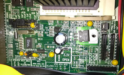
I assumed the TO-220 package on the board near the 3.3v/5v jumper would be a voltage regulator but it isnt, its a TIP31C power transistor (3.3v is jumper open, 5v is jumper closed)

Changing the jumper does change the voltage on the emitter, and the voltage on the emitter is the same as the VCC in the socket.

I was trying to work out how I'd alter the voltage here, ideally without removing the working TIP31C.
I was wondering (slightly optimistically!) if adding resistor(s) across the jumper would affect the output voltage - it does if there is no load (adding ~40 ohms raises the voltage to about 3.8v) but as soon as you put a CPU in, the voltage locks to 3.35v as though the jumper was open. I faffed about with various resistances to see if it made any difference - increasing the resistance did increase the voltage without a cpu load, but as soon as the CPU was in it locked to a stable 3.35v.

My electronics knoweldge is fairly limited - I'd appreciate some advice! Is there a sane way of adjusting the voltage or do I just have to live with it?

(I was using a 5v AMD 486 DX2 when testing so I didnt fry my 3.3v CPU whilst mucking about!)
(Also, FWIW, I tried 50MHz bus with 3x multiplier but my video card cant cope with the 50MHz bus - POST card gets stuck in the video intialisation part of the codes and no POST - clock to 40MHz and it is fine)

Thanks!

V4P895P3 VLB Motherboard AMD 486 133MHz
64mb RAM, CF 4Gb HDD,
Realtek 8019 ethernet + XT-IDE bios ROM, ES1869 soundcard, VLB Cirrus Logic GD5428 1mb VGA

440bx MSI 6119, modified slocket , Tualitin Celeron 1.2Ghz 256mb SD-RAM, CF 4GB HDD, FX5200 gfx

Reply 1 of 11, by quicknick

User metadata
Rank Oldbie
Rank
Oldbie

Should be possible, but not by altering the jumper as I suspect the only thing it does is to short out the series transistor when set to 5 volts.

I think you will have to play with some resistors that bias the base of the TIP31C, or it could be something more complicated using a voltage reference. Please post a close-up photo of the transistor and the area surrounding it.

Reply 2 of 11, by squelch41

User metadata
Rank Member
Rank
Member
quicknick wrote on 2020-11-22, 20:36:

Should be possible, but not by altering the jumper as I suspect the only thing it does is to short out the series transistor when set to 5 volts.

I think you will have to play with some resistors that bias the base of the TIP31C, or it could be something more complicated using a voltage reference. Please post a close-up photo of the transistor and the area surrounding it.

Attached, thanks

Attachments

  • Voltage.jpg
    Filename
    Voltage.jpg
    File size
    1.94 MiB
    Views
    393 views
    File license
    Public domain

V4P895P3 VLB Motherboard AMD 486 133MHz
64mb RAM, CF 4Gb HDD,
Realtek 8019 ethernet + XT-IDE bios ROM, ES1869 soundcard, VLB Cirrus Logic GD5428 1mb VGA

440bx MSI 6119, modified slocket , Tualitin Celeron 1.2Ghz 256mb SD-RAM, CF 4GB HDD, FX5200 gfx

Reply 3 of 11, by quicknick

User metadata
Rank Oldbie
Rank
Oldbie

Seems there's a LM431 involved, so I feel that's a bit over my head. But check its datasheet and try to trace out the schematic, find out the two resistors connected to the Ref pin - with a little effort you can replace one of them with a variable resistor and obtain a wide range of voltages...

Reply 4 of 11, by squelch41

User metadata
Rank Member
Rank
Member

Long shot, but does anyone know of a schematic for the board (or schematic library that might have it) online?

V4P895P3 VLB Motherboard AMD 486 133MHz
64mb RAM, CF 4Gb HDD,
Realtek 8019 ethernet + XT-IDE bios ROM, ES1869 soundcard, VLB Cirrus Logic GD5428 1mb VGA

440bx MSI 6119, modified slocket , Tualitin Celeron 1.2Ghz 256mb SD-RAM, CF 4GB HDD, FX5200 gfx

Reply 6 of 11, by squelch41

User metadata
Rank Member
Rank
Member
computerguy08 wrote on 2020-11-23, 11:22:

The best you can do is find a reference schematic for the LM431 IC. Finding a schematic for that motheboard is next to impossible.

Thought it was a bit optimistic 😉

V4P895P3 VLB Motherboard AMD 486 133MHz
64mb RAM, CF 4Gb HDD,
Realtek 8019 ethernet + XT-IDE bios ROM, ES1869 soundcard, VLB Cirrus Logic GD5428 1mb VGA

440bx MSI 6119, modified slocket , Tualitin Celeron 1.2Ghz 256mb SD-RAM, CF 4GB HDD, FX5200 gfx

Reply 8 of 11, by squelch41

User metadata
Rank Member
Rank
Member

Simple is in the eye of the beholder! 😉

V4P895P3 VLB Motherboard AMD 486 133MHz
64mb RAM, CF 4Gb HDD,
Realtek 8019 ethernet + XT-IDE bios ROM, ES1869 soundcard, VLB Cirrus Logic GD5428 1mb VGA

440bx MSI 6119, modified slocket , Tualitin Celeron 1.2Ghz 256mb SD-RAM, CF 4GB HDD, FX5200 gfx

Reply 9 of 11, by quicknick

User metadata
Rank Oldbie
Rank
Oldbie

Okay, here's the relevant bit from the datasheet:

LM431.jpg
Filename
LM431.jpg
File size
23.28 KiB
Views
307 views
File license
Fair use/fair dealing exception

Vref is a fixed 2.5V. I think R5 (1.2Kohm) and R15 (3Kohm) from your board correspond to R1 and R2 on the above schematic. If I'm right, replacing R5 with a 1.5Kohm will yield a voltage of around 3.75V, or 4 volts when using 1.8Kohm. Or replace it with a 3.3Kohm multi-turn trimpot and dial-in any voltage from an useless 2.5V up to (almost) full 5V.
Of course there's a chance I'm wrong and your board will go up in flames, that's why I suggested you to study the datasheet and trace the connections around the LM431 😉

Reply 10 of 11, by squelch41

User metadata
Rank Member
Rank
Member
quicknick wrote on 2020-11-24, 00:22:
Okay, here's the relevant bit from the datasheet: LM431.jpg Vref is a fixed 2.5V. I think R5 (1.2Kohm) and R15 (3Kohm) from your […]
Show full quote

Okay, here's the relevant bit from the datasheet:
LM431.jpg
Vref is a fixed 2.5V. I think R5 (1.2Kohm) and R15 (3Kohm) from your board correspond to R1 and R2 on the above schematic. If I'm right, replacing R5 with a 1.5Kohm will yield a voltage of around 3.75V, or 4 volts when using 1.8Kohm. Or replace it with a 3.3Kohm multi-turn trimpot and dial-in any voltage from an useless 2.5V up to (almost) full 5V.
Of course there's a chance I'm wrong and your board will go up in flames, that's why I suggested you to study the datasheet and trace the connections around the LM431 😉

Thanks - I was a bit confused about which circuit on the data sheet was the correct one to follow (No engineering training, as I am sure is obvious!!)

I was thinking R5 and R15 were the voltage dividers too.
There is 0 ohms between the Vref pin of the LM485 and one end of R5 and also of R15

Referenced to ground:
The ouput from the LM485 cathode is 4.1v and that is the same voltage as is fed to the TIP31C base (4.75v is on the collector == power supply output on the 5v line; 3.4v on the emitter)
Voltages on the Vref pin of the LM485 is 2.45v
on R5, on the side wired directly to the LM485 is 2.45v and the other side is 3.4v
R15 is 2.45v on the LM485 side and 0v on the other side

So that is all as it should be if those are the voltage dividers shown in the data sheet diagram I think?

Also, then if, as a test, I piggybacked a 15k resistor over the 3k resistor, that should give a resistance of 2.5k and a voltage output from the the TIP31C of 3.7v?

V4P895P3 VLB Motherboard AMD 486 133MHz
64mb RAM, CF 4Gb HDD,
Realtek 8019 ethernet + XT-IDE bios ROM, ES1869 soundcard, VLB Cirrus Logic GD5428 1mb VGA

440bx MSI 6119, modified slocket , Tualitin Celeron 1.2Ghz 256mb SD-RAM, CF 4GB HDD, FX5200 gfx

Reply 11 of 11, by squelch41

User metadata
Rank Member
Rank
Member

(so wire to vref pin and then a ground point - avoid soldering on the board)

V4P895P3 VLB Motherboard AMD 486 133MHz
64mb RAM, CF 4Gb HDD,
Realtek 8019 ethernet + XT-IDE bios ROM, ES1869 soundcard, VLB Cirrus Logic GD5428 1mb VGA

440bx MSI 6119, modified slocket , Tualitin Celeron 1.2Ghz 256mb SD-RAM, CF 4GB HDD, FX5200 gfx