VOGONS


Asus USB/MIR reverse engineering

Topic actions

First post, by sapperlott

User metadata
Rank Newbie
Rank
Newbie

Hi!

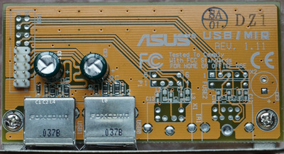
I got myself a used Asus SP97 on eBay. As some of you may already know, this is one of the Asus boards that have support for a PS/2 mouse but require the Asus USB/MIR adapter board to provide the proper PS/2 jack for it. There are plenty of USB/MIR boards available on eBay but pretty much all of those are the newer kind that only have the two USB ports populated - the PS/2 and infrared port footprints still exist on the PCB but remain unpopulated.

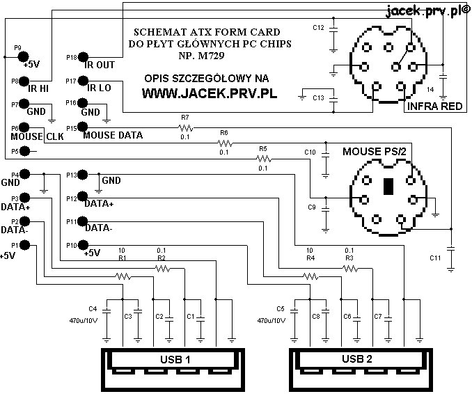
Since not that many components are missing it should be fairly easy to just add them and hence get a fully working USB/MIR adapter in the process. The biggest hurdle here is that the component values for the missing resistors and inductors are unknown. Hence my question here:

Is someone owning a fully populated USB/MIR board willing to do one of these things (in order of difficulty)?
- Provide high-res photos of the components around the PS/2 / infrared ports
- Measure the component values in-circuit (ideally using an LCR meter)
- Donate a fully populated USB/MIR board they don't need for analysis (ship to Germany)
- Desolder the PS/2 (any maybe infrared) port related components and measure each of their values out of circuit

I know that there are 3rd party "ATX Form Cards" out there but their availability in Germany isn't great either.

Reply 1 of 34, by Hirsch

User metadata
Rank Newbie
Rank
Newbie

I'm looking for this information, too. Asus USB/MIR boards with only USB part populated are rather common and cheap, so it makes sense to add the "missing" parts on one of these. First of all I made a highres photo of my card and added some labels which are difficult to read. I was able to measure or read the values of the following parts:
CE1, CE2 = 1000 µF, 6.3V
L0, L4 = 10 Ohm
L1, L5 = 4.3 Ohm
(Labeling resistors with "L " is rather confusing.)

I was unable to measure the capacitors with my ESR meter inside the circuit:
C1 is parallel to CE1 and C6 is parallel to CE2 (both buffering +5V)
C2, C3, C4, C5 are shunt capacitors connecting the USB signal lines with GND.
(I think that I have to desolder the capacitors for measuring because they aren't labeled.)

Altogether I think that we need a "donor board" for reverse engineering where to desolder the parts before measuring. I've been looking for one at Ebay for a while but haven't found one, yet.

Attachments

  • Asus-USB-MIR.jpg
    Filename
    Asus-USB-MIR.jpg
    File size
    1.41 MiB
    Views
    2349 views
    File license
    Fair use/fair dealing exception

Reply 3 of 34, by Horun

User metadata
Rank l33t++
Rank
l33t++

Probably not much help but it was common to parallel a 0.1uF ceramic cap with the High uF buffer caps on lots of old circuits....so C1 and C6 could be 0.1....

Hate posting a reply and then have to edit it because it made no sense 😁 First computer was an IBM 3270 workstation with CGA monitor. Stuff: https://archive.org/details/@horun

Reply 4 of 34, by wiretap

User metadata
Rank Oldbie
Rank
Oldbie

Oh, this adapter with PS/2 is available for purchase.. I just ordered one to reverse engineer for the future.

Same design, just not branded "Asus".
http://www.cablesonline.com/usbatxforcar.html

My Github
Circuit Board Repair Manuals

Reply 5 of 34, by Zero_sugar

User metadata
Rank Newbie
Rank
Newbie
wiretap wrote on 2021-12-22, 01:16:

Oh, this adapter with PS/2 is available for purchase.. I just ordered one to reverse engineer for the future.

Same design, just not branded "Asus".
http://www.cablesonline.com/usbatxforcar.html

I use one of those with my P5A-b and it works great.

Reply 6 of 34, by BitWrangler

User metadata
Rank l33t++
Rank
l33t++

Let us know if that store is alive, it's got a Mary Celeste vibe about it to me.

Unicorn herding operations are proceeding, but all the totes of hens teeth and barrels of rocking horse poop give them plenty of hiding spots.

Reply 9 of 34, by Hirsch

User metadata
Rank Newbie
Rank
Newbie
wiretap wrote on 2021-12-22, 00:54:

The L0, L1, L4, L5 etc are inductors.

The ones with 4R3 are 4.3uH. The ones labeled 100 are 10uH.

I only agree with you up to the point that every conductor is an inductor, too. I've measured the inductivity and the resistance with an LCR meter. The result is:
L0 = 8.4 µH
L0 = 10 Ω
L1 = 6.3 µH
L1 = 4.3 Ω
(note: The inductivity of the measuring cables itself is 42 µH which indicates how small the values measured are.)

When I consider my measurings and that what's written on the SMD parts it turns out that this MUST be resistors. (Labeling resistors with "L" on a PCB is very confusing.)

Reply 10 of 34, by Hirsch

User metadata
Rank Newbie
Rank
Newbie
wiretap wrote on 2021-12-22, 01:16:

Oh, this adapter with PS/2 is available for purchase.. I just ordered one to reverse engineer for the future.

Same design, just not branded "Asus".
http://www.cablesonline.com/usbatxforcar.html

I found this one, too. They charge insane $65 for shipping to Germany with FedEx International (only shipping option to Germany). Mouser charges $20 for FedEx Express (or free shipping if order is >$50) in comparison to this. I'm glad that someone from the USA ordered this for reverse engineering. Thank you very much 😀

Reply 11 of 34, by wiretap

User metadata
Rank Oldbie
Rank
Oldbie
Hirsch wrote on 2021-12-22, 12:42:
I only agree with you up to the point that every conductor is an inductor, too. I've measured the inductivity and the resistance […]
Show full quote
wiretap wrote on 2021-12-22, 00:54:

The L0, L1, L4, L5 etc are inductors.

The ones with 4R3 are 4.3uH. The ones labeled 100 are 10uH.

I only agree with you up to the point that every conductor is an inductor, too. I've measured the inductivity and the resistance with an LCR meter. The result is:
L0 = 8.4 µH
L0 = 10 Ω
L1 = 6.3 µH
L1 = 4.3 Ω
(note: The inductivity of the measuring cables itself is 42 µH which indicates how small the values measured are.)

When I consider my measurings and that what's written on the SMD parts it turns out that this MUST be resistors. (Labeling resistors with "L" on a PCB is very confusing.)

To me, it looks like the standard IEEE implementation of USB EMC protection using an LC tee-circuit. It would be extremely odd to ignore the silkscreen from a design perspective, especially since it isn't the first rev of the board.

I'll check mine once it arrives.

My Github
Circuit Board Repair Manuals

Reply 13 of 34, by wiretap

User metadata
Rank Oldbie
Rank
Oldbie

If you're sure of that, it is a crackhead design, because the resistors should be around 27ohm if that was to be an RC t-circuit. They are in series with the data lines, as they are on the matched impedance pair seen from the squiggly traces.

FYI, I have used plenty of 0805 inductors with markings.

My Github
Circuit Board Repair Manuals

Reply 14 of 34, by BitWrangler

User metadata
Rank l33t++
Rank
l33t++
wiretap wrote on 2021-12-22, 04:36:

Last time I ordered from there was about 8 months ago for some SCSI stuff for my Amiga, so they should still be open I hope..

Thanks, it looks 5 years out of date somehow.

Unicorn herding operations are proceeding, but all the totes of hens teeth and barrels of rocking horse poop give them plenty of hiding spots.

Reply 15 of 34, by Sphere478

User metadata
Rank l33t++
Rank
l33t++

iWill p55xb2 has a reiser like this that I’ve never been able to find. It’s a different card entirely though.

I documented it the best I could in the thread in my signature and on ultimate retro motherboard database. But being different I’m pretty sure it’s not of much help to you.

I found it more useful to tap into the port on the motherboard though because I wanted more ports and wired it into a internal usb hub

I think there are probably a lot of people looking for these though and a usb/ps2 reiser project would be a good idea if someone wanted to render the gerber file it could even be designed to work with DIN and mini DIN as well as have a usb hub on it for more ports.

Sphere's PCB projects.
-
Sphere’s socket 5/7 cpu collection.
-
SUCCESSFUL K6-2+ to K6-3+ Full Cache Enable Mod
-
Tyan S1564S to S1564D single to dual processor conversion (also s1563 and s1562)

Reply 17 of 34, by BitWrangler

User metadata
Rank l33t++
Rank
l33t++

Good find, thanks!

Unicorn herding operations are proceeding, but all the totes of hens teeth and barrels of rocking horse poop give them plenty of hiding spots.

Reply 19 of 34, by Sphere478

User metadata
Rank l33t++
Rank
l33t++
wiretap wrote on 2021-12-23, 16:47:

Nice. I'll build a KiCAD project based off that one, with a 3D printable bracket.

Add a usb hub to it! :p

Sphere's PCB projects.
-
Sphere’s socket 5/7 cpu collection.
-
SUCCESSFUL K6-2+ to K6-3+ Full Cache Enable Mod
-
Tyan S1564S to S1564D single to dual processor conversion (also s1563 and s1562)