VOGONS


First post, by draetheus

User metadata
Rank Newbie
Rank
Newbie

The motherboard for my overkill 98 SE rig came in yesterday (ECS P4M800PRO-M 2.0). Overall it's in very good condition, but unfortunately 3 of the 4 large VRM caps appear to be bulging slightly. I'm not experienced with this type of thing at all. Is it ok to at least put in a few hours of install and testing before thinking of a recap? Or does this need immediate recap? If the latter, is this simple enough for a soldering beginner or would I need to pay to have this done?

Attachments

Reply 1 of 8, by Cyberdyne

User metadata
Rank Oldbie
Rank
Oldbie

NOPE! Recap immediately! Those may burts any time. And your system is not stable.

I am aroused about any X86 motherboard that has full functional ISA slot. I think i have problem. Not really into that original (Turbo) XT,286,386 and CGA/EGA stuff. So just a DOS nut.
PS. If I upload RAR, it is a 16-bit DOS RAR Version 2.50.

Reply 2 of 8, by dionb

User metadata
Rank l33t++
Rank
l33t++

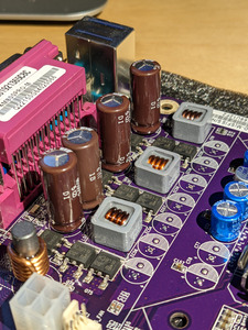
As soon as just one cap of a given type shows the slightest sign of bulging, leaking or otherwise physically changing, it needs replacing and so do all other caps of same type on the board. Usually physical symptoms only become visible after significant electrical degradation has already occurred.

That said: will this board explode and set fire to your house if you just briefly plug it in - probably not, although you don't want to have your eyes anywhere near those caps as you might get a corrosive, toxic fountain coming out of them. Depending on what I wanted, I might risk doing some testing, but then again, it doesn't really add anything: if it's not booting, or booting but not stable, the caps are most likely implicated and need swapping. If it is booting and stable, it won't be for much longer with caps in this state, so the caps need swapping... I'd just swap the caps.

As for how difficult - that depends on your tools. This board is new enough to have ROHS lead-free solder, which is a PITA that needs a lot more heat than older toxic lead solder.

What I would do if this was my board:

Prerequisites
- replacement caps, good brand (Panasonic, Nichicon, Sanyo etc) from a reputable electronics vendor. Ensure capacitance and pitch (pin spacing) are exact matches, and that rated voltage is at least the same. Ideally you want to match ESR as well, but probably these shitty caps never lived up to spec (if you can find it...) anyway, so just go for generic low-ESR caps and you should be good.
- a decent soldering iron. I'd say at least 30W because ROHS and ground plane.
- thin fresh solder, preferably easy-to-use leaded stuff
- flux
- if possible a desoldering pump (simple plastic spring-loaded one is probably good enough). Some people swear by copper braid, but it doesn't generally work for me, at least not as a full alternative for a pump

Desoldering
- clean the underside of board well
- apply flux to the pins
- solder blobs of fresh solder onto the pins
- heat the first pin well. You want the new solder to mix with the old stuff and make it softer
- when it looks like everything around a pin is liquid, suck it out with the pump, apply braid or failing any of that, try physically moving the cap (lean away from the side you're working on) to pull the pin out. You'll notice that the + goes much faster than the -, which is connected to a big ground plane, that sucks up huge amounts of heat. If this doesn't work, solder on another blob of new solder, heat it all a bit longer and try again.
- repeat for second pin
- after getting the cap out, clean up the holes. You might need a few more drops of fresh solder for this. Suck/braid out as much as you can. At the very least you need enough of a depression to get the new cap leg into when you start soldering, but preferably the whole hole should be clean with no mess around it on the PCB either.
- repeat for other three caps.
- dispose of old caps as chemical waste.

Soldering (the easy bit)
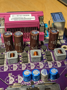
- get new cap and line it up correctly. The stripe on the cap is the negative (-) pole and MUST be lined up with the negative side (white semicircle in this case) on the board. Failure to get this right results in exploding cap at first power on!
- if you managed to completely clean the holes, then it's easy:
-- stick in new cap
-- apply flux
-- heat first leg
-- apply solder to the hot leg until it melts & fills the hole
-- repeat for second leg
-- trim off excess leg length
- didn't manage to completely clean the holes? then more fun:
-- apply flux and blob of new solder to blocked hole on bottom of board
-- hold cap in place on top side with light pressure (so it will sink through hole as soon as possible, but not so hard you bend the leg)
-- heat the new solder blob over hole on bottom of board while keeping pressure on cap
-- if all goes well, the leg should go through once solder in hole is soft enough
-- repeat for other leg
(you may find not having a third arm is a bit of a handicap while performing this sort of shenanigans... 😉 )
Either way, when it's done, clean off any solder and flux residue. Then you're ready to test.

If you've never done this before, I'd strongly recommend practicing twice first on bits of electronics you don't mind ruining:
1) something from before 2000, with good 0ld leaded solder (easy)
2) something from after 2003, with ROHS certification (hard, comparable to the motherboard)

Reply 3 of 8, by mr.cat

User metadata
Rank Member
Rank
Member

@dionb, that's very nice writeup, thank you!

I'd add that if you're unsure, maybe spend some time reading badcaps.net to see what you're up against (they have some hints about tools etc there).
What is the history of the board? If you know it was working before, maybe it will work for another 5 mins more (or maybe not...)

Reply 4 of 8, by douglar

User metadata
Rank Oldbie
Rank
Oldbie

Nice write up.

It's pretty tough to get that lead free solder to flow. I had to get a new soldering pen that would go over 400c to get the caps off my Athlon XP board, while my old reliable 1980's soldering pen was able to get components of a 486 board without too much trouble.

Reply 5 of 8, by draetheus

User metadata
Rank Newbie
Rank
Newbie
mr.cat wrote on 2021-01-14, 15:19:

@dionb, that's very nice writeup, thank you!

I'd add that if you're unsure, maybe spend some time reading badcaps.net to see what you're up against (they have some hints about tools etc there).
What is the history of the board? If you know it was working before, maybe it will work for another 5 mins more (or maybe not...)

I actually haven't tested it yet, I'm still waiting for my CPU + HSF to arrive. History unknown as the ebay seller appears to be one of those big lot recyclers.

Reply 6 of 8, by Eep386

User metadata
Rank Member
Rank
Member

Those caps appear to be Chemi-con KZG, a repeat offending series. KZG rated under 16V tend to be very unstable over time, especially when subject to > 50c heat over a long period of time (a common occurrence in VRMs near the CPU). 16V and higher rated KZG don't seem to go bad as often, but once one KZG fails you might as well replace all the KZGs.

AFAIK modern aluminum electrolytic replacements for KZG with the same ESR value are no longer in production, so your best bet is to replace them with polymer caps of similar rating. Don't worry about buying more caps from Chemi-con, the KZG/KZJ were just a 'bad series' from them, and the rest of their caps seem pretty good. I use KY and KZE myself.

Life isn't long enough to re-enable every hidden option in every BIOS on every board... 🙁

Reply 7 of 8, by TheMobRules

User metadata
Rank Oldbie
Rank
Oldbie

Judging by the brown color those caps are Chemi-con KZG or KZJ. These series are problematic and ALWAYS fail early, despite being from a reputable Japanese brand, so you'll definitely want to replace them all.

Also, they're extremely low ESR so you need to find adequate replacements, probably polymers would work fine given that it's a 775 board. You can read up a bit on polymodding, there are some threads here and in badcaps.net as mentioned above.

If you don't feel comfortable soldering, keep in mind those boards usually sink a lot of heat and have tiny pads, which makes the process of removing the caps and clearing the holes very difficult without proper tools and some experience.

EDIT: Eep386 beat me to it 😀

Reply 8 of 8, by mr.cat

User metadata
Rank Member
Rank
Member
draetheus wrote on 2021-01-14, 15:36:
mr.cat wrote on 2021-01-14, 15:19:

What is the history of the board? If you know it was working before, maybe it will work for another 5 mins more (or maybe not...)

I actually haven't tested it yet, I'm still waiting for my CPU + HSF to arrive. History unknown as the ebay seller appears to be one of those big lot recyclers.

Right. Better to be on the safe side then. Best of luck!