First post, by DNSDies

- Rank
- Member
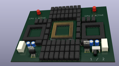
Just a weird idea I had, but would it be possible to put an interposer board on a CPU socket with 2 additional CPU sockets, and be able to have, say, a switch that prevents vcc to one of the CPUs so you could pick which CPU you're using before powering on the computer?
Like, say I wanted a Super Socket 7 machine with a Pentium 100mhz AND an AMD K6-III 450mhz, and with the push of a button, I could swap CPUs without opening the case.
Or say I had a motherboard that supported a 386 and 486 CPU socket, and wanted to have a way to isolate the 486 CPU via an interposer PCB and a switch that would physically disable the multiple VCC pins.
Would this work, or would the address/data lines and various other pins need to be separated as well?
Because I don't think it's possible to find a 200-300 input switch. But a 4-6 input switch? That's much easier.
This is a dumb idea.