VOGONS


First post, by 4xtx

User metadata
Rank Member
Rank
Member

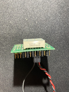
I recently got a generic case (circa 486 era) which has a LED Speed Display (can display up to 199).
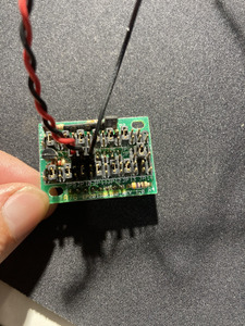
Previous owner cut all the cables and the only one connected to the display was a 3-pin cable.
Assuming it was 5V + GND (and another GND?) I simply detached this and plugged in the 2 pin AT power connector.
Upon powering on it displayed "100" and I figured this was because the bottom row was initially configured the same as the top.
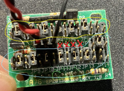
I adjusted the jumpers on the bottom row (after I took these photos) and it now reads "LO"

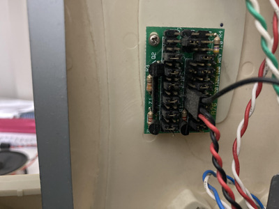
The problem here is I cannot seem to toggle either manually (using a jumper) or automatically using TURBO LED signal from motherboard.
It will only display "LO" and won't switch to "100" regardless of the TURBO LED state.
I can't find any schematics or info on this board - wondering if someone might have some info?

Board Reads: A76 EP20130R100 REV 1.0

Also: I note there's a very short TURBO LED wire on the case presumably this plugs into the board.

Attachments

  • LEDTOP.jpg
    Filename
    LEDTOP.jpg
    File size
    1.72 MiB
    Views
    282 views
    File license
    Public domain
  • LEDBACK2.jpg
    Filename
    LEDBACK2.jpg
    File size
    1.7 MiB
    Views
    282 views
    File license
    Public domain
  • LEDBACK.jpg
    Filename
    LEDBACK.jpg
    File size
    1.16 MiB
    Views
    282 views
    File license
    Public domain

YT: https://www.youtube.com/@techdistractions

Reply 1 of 7, by Warlord

User metadata
Rank l33t
Rank
l33t

you have to rig the switch to the display. the switch controls what it displays. when switch is up or down it will change the display. the numbers on the dipsplay are just programed using jumpers on the back.
the turbo led signal from the motherboard isn't for the display its for when u dont have a display and it just turns a simple led like the ones for power or hdd on and off.

the actual turbo header on the motherboard is just open or closed for turbo on or turbo off.

this is how mines wired obviously your display is alittle different.

the yellow circle programs high the blue programs low the red x marks are the headers that you need to rig the switch to. the switch plug into display and to mobo header

Attachments

  • LEDBACK2.jpg
    Filename
    LEDBACK2.jpg
    File size
    345.53 KiB
    Views
    267 views
    File license
    Fair use/fair dealing exception
Last edited by Warlord on 2021-02-07, 10:11. Edited 1 time in total.

Reply 2 of 7, by 4xtx

User metadata
Rank Member
Rank
Member
Warlord wrote on 2021-02-07, 09:58:

you have to rig the switch to the display. the switch controls what it displays. when switch is up or down it will change the display. the numbers on the dipsplay are just programed using jumpers on the back.

Thanks for the reply - I find this confusing as the TURBO SW cable from the case panel is significantly longer than the TURBO LED and looks like it's designed to go to the motherboard as a 3 pin switch.
I do get what your saying and just tested every possible combination on the middle row to no avail using the TURBO SW 3 pin

YT: https://www.youtube.com/@techdistractions

Reply 3 of 7, by Warlord

User metadata
Rank l33t
Rank
l33t

the yellow circle programs high the blue programs low the red x marks are the headers that you need to rig the switch to. the switch plug into display and to mobo header

the red and black wires look like +5v to me unless u have that wrong
file.php?id=102398&mode=view

file.php?id=91017&mode=view

Reply 4 of 7, by Warlord

User metadata
Rank l33t
Rank
l33t

check this site but i dont see yours
http://www.minuszerodegrees.net/led_speed_dis … eed_display.htm

2 ways

Attachments

  • turbo_switching_1.jpg
    Filename
    turbo_switching_1.jpg
    File size
    74.37 KiB
    Views
    255 views
    File license
    Fair use/fair dealing exception

Reply 5 of 7, by 4xtx

User metadata
Rank Member
Rank
Member
Warlord wrote on 2021-02-07, 10:18:

check this site but i dont see yours
http://www.minuszerodegrees.net/led_speed_dis … eed_display.htm

2 ways

Yep, I did check and couldn't find it either.
I do think this one's set up to have the middle row pins as +|-|N|1|2|3|4
I also believe every 2nd Jumper is for the LOW reading not top and bottom as per other units.
Hypothesis is that 1+2 = TURBO LED from motherboard (jumper wire) and 3+4 are TURBO LED to case panel (the short cable).
Given there was only 4 pins free with the original +, - & N cable installed I reckon it's not looking for a switch but anyway, I tested:

Connecting a switch to any combination of N, 1-4 does not make any difference. Neither does the equivalent of jumpering them (to cause a short/switch).
Connecting the TURBO LED from the motherboard to any of the N, 1-4 pins makes no difference either.

I've checked that the TURBO LED from motherboard does in fact turn off and on using a spare LED I have. It is reacting to the TURBO SW on the motherboard.
Currently the board is configured to display "66" when turbo is on and has nothing jumpered for when turbo is off (blank).

YT: https://www.youtube.com/@techdistractions

Reply 6 of 7, by Warlord

User metadata
Rank l33t
Rank
l33t

that is becasue i think you are powering the display from the motherboard turbo led. Thats why it shows 66 when turbo is on and nothing when turbo is off. So you are drawing 5v from the LED header off the board. instead of 5v

off the power supply. I tried explaining this before that the LED header atleast on my board is just a LED that turns off and on when turbo is off and on. Its unrelated. so when u de turbo its turning the led off. The display itself needs constant 5v power all the time. Just like the other ones from that page.

your display should have H pin L pin G pin jumpering H + g will give you high jumpering L + g will give u low. 2 pins are for 5v + ground. That is 5 pins total. Minee had 6 pins and one was un used. yours has 7 pins. my guess is not all 7 are connected.

on mine my switch connects to the display and the mother board. yours the way you have it is your switch is just connected to you board and you are feeding 5v to your display from the led header and thats why it doesnt work.

id be willing to be that on yours. the far left 2 are +5v and ground. The single black is a ground. Then out of the 4 on the right one is high and one is low. if you eliminate that single black and bridge that pin and 1 of the other 4 you will get high or low.

you have to make some custom cables and rewire it if you want it to work with you board. Molex off the psu and splice in +5 and g. Get rid of the 3 wire thing. Then figure out the H and Low pins by grounding them to the single wire by iteslf then wire H G L to your switch and just H+ G to the boardon the other side of the switch.

Reply 7 of 7, by 4xtx

User metadata
Rank Member
Rank
Member
Warlord wrote on 2021-02-07, 12:15:

that is becasue i think you are powering the display from the motherboard turbo led. Thats why it shows 66 when turbo is on and nothing when turbo is off. So you are drawing 5v from the LED header off the board. instead of 5v

Apologies for not being clear before - I did remove the 3 pin cable and replace it with one directly cabled to the 5v+ and - on my AT power supply (spliced off at Molex).
It does need some more experimentation though I will do so and post some more helpful photos 😀
Thank you for your replies, very much appreciated!

YT: https://www.youtube.com/@techdistractions