VOGONS


First post, by tony359

User metadata
Rank Member
Rank
Member

Hello all

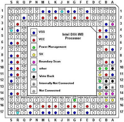
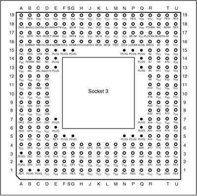
I was wondering if someone could help me with the pinout of a Socket 3. I am a bit confused by the schematics I find online.

Can someone confirm which side should I see the attached pinout diagram please? Processor side or back of the board side?

Also, is it ok to find 5V on Socket 3 even though the VCC is set to 3.3V? What I mean is: I see 3.3V on VCC pins but also 5V on many other pins. Would that work with my DX4 CPU?

Thank you a lot!
Tony

Attachments

  • socket3.gif
    Filename
    socket3.gif
    File size
    70.95 KiB
    Views
    217 views
    File license
    Public domain

My Youtube channel: https://www.youtube.com/@tony359

Reply 1 of 2, by mpe

User metadata
Rank Oldbie
Rank
Oldbie

DX4 is a 3.3V CPU. Thus you should see 3.3V between VCC and VSS pins but it obviously operates in 5V environment as the rest of the motherboard is 5V. Thus you'll see 5V voltage elsewhere.

Your scheme seems to be for a socket. It has way more pins than the 486 CPU as outermost pins are for Pentium Overdrive (P24T pinout). Furthermore you won't probably find most of these "plug" pins on any real socket. That's why the scheme might be confusing

I personally prefer this scheme:

Intel DX4-WB.jpg
Filename
Intel DX4-WB.jpg
File size
91.75 KiB
Views
197 views
File license
CC-BY-4.0

Which is the orientation you get when you look from top or if you place PGA168/169 CPU to the Socket 3:

DSC_9099.jpeg
Filename
DSC_9099.jpeg
File size
726.2 KiB
Views
194 views
File license
CC-BY-4.0

Blog|NexGen 586|S4