VOGONS


First post, by Paal

User metadata
Rank Newbie
Rank
Newbie

Hi!

I know the subject has been brought up before, but the topics I have read has not made be any wiser than before, so here goes!

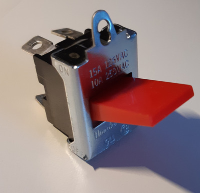
I have a full tower AT 486 computer with the red rocker switch.
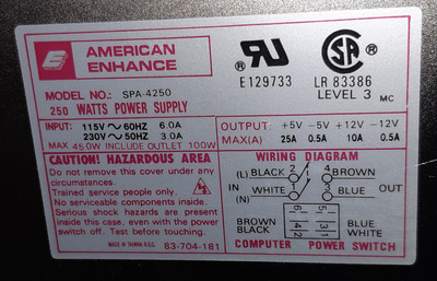
I have replaced the AT power supply with a new old stock AT power supply, AE, model SPA-4250

I have the wiring diagram and the cables are white, blue, black and brown. The green yellowed cable is for the ground.
I tried to wire it just like the old power supply and used it as a reference. I have read that you can really mess up if you are doing it the wrong way.
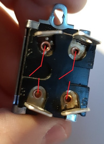
Initially, I put the white cable on the upper left on the rocker switch as (1) seen in the picture, the black to the lower left, blue cable right next to the white cable and the brown at the lower right.
Fired it up and no response, the light in the room went out and I needed to switch the circuitbreaker on again.

The power supply works with the push button switch it came provided with and it worked when I got back to that push button switch.

Can someone help me out, what have I missed?
Either I have mixed the wiring or the switch itself isn't compatible.

Attachments

  • wiringlayout.jpg
    Filename
    wiringlayout.jpg
    File size
    222.5 KiB
    Views
    1309 views
    File comment
    Numbers 1 through 6
    File license
    Fair use/fair dealing exception
  • rockerpwrswitch.jpg
    Filename
    rockerpwrswitch.jpg
    File size
    499.44 KiB
    Views
    1309 views
    File comment
    Himake power switch
    File license
    Fair use/fair dealing exception
  • americanenhancespa-4250.jpg
    Filename
    americanenhancespa-4250.jpg
    File size
    888.87 KiB
    Views
    1309 views
    File comment
    Works with the push button switch
    File license
    Fair use/fair dealing exception

Reply 1 of 9, by majestyk

User metadata
Rank Oldbie
Rank
Oldbie

Black and white to pins 2 an5, brown and blue to pins 3 and 6 of the rocking switch.
The way you connected them shorted the mains when switching on.

The question is whether the switch has been damaged.

Last edited by Stiletto on 2021-02-15, 00:18. Edited 1 time in total.

Reply 2 of 9, by Paal

User metadata
Rank Newbie
Rank
Newbie
majestyk wrote on 2021-02-14, 09:29:

Black and white to pins 2 an5, brown and blue to pins 3 and 6.
The way you connected it shorted the mains when switching on.

The question remains is whether the switch has been damaged.

Thanks for the answer!

Black for pin 2
White for pin 5
Brown for pin 3
Blue for pin 6

The rocker power switch was working before I replaced the power supply, if you are referring to the switch. If I have shorted the mains when switching on, can it be the rocker power switch went with the short?
I do believe the black dirt on pin 1 was there before, but I didn't really pay attention to it.

Last edited by Stiletto on 2021-02-15, 00:18. Edited 1 time in total.

Reply 3 of 9, by digistorm

User metadata
Rank Member
Rank
Member

It is possible that the contacts are fused together, or that the contacts have been burnt away. It would be best to use a multimeter to measure which contacts are connected when you pull the switch, before you hook it up to mains. Then you can also verify that is it still working.

Reply 4 of 9, by Paal

User metadata
Rank Newbie
Rank
Newbie
digistorm wrote on 2021-02-14, 09:52:

It is possible that the contacts are fused together, or that the contacts have been burnt away. It would be best to use a multimeter to measure which contacts are connected when you pull the switch, before you hook it up to mains. Then you can also verify that is it still working.

I have a multimeter and I'm up for the task of measuring and testing the switch. How do I proceed to verify it, do I check for continuity between the pins in both ON and OFF position?

Reply 5 of 9, by digistorm

User metadata
Rank Member
Rank
Member

In the 'off' position, no leg should be connected to any other leg. In the 'on' position, one leg should be connected to one other leg. So there should be two pairs of legs that are connected in the 'on' position. The way you should connect the switch is that you connect the incoming mains voltage wires (brown and blue in europe) to two legs that are never connected to each other (otherwise you will short the mains when you turn the switch on) and you connect the outgoing wires that go to the power supply to the remaining legs that should also never be connected to each other. An AT mains switch works internally like two switches that operate at the same time. A bit like this:

    ~  *----*/  *------*
MAINS PSU
~ *----*/ *------*

I hope it makes sense. I'm sure there is a better drawing or picture somewhere online, together with a better explanation.

Reply 6 of 9, by Paal

User metadata
Rank Newbie
Rank
Newbie
digistorm wrote on 2021-02-14, 10:16:
In the 'off' position, no leg should be connected to any other leg. In the 'on' position, one leg should be connected to one oth […]
Show full quote

In the 'off' position, no leg should be connected to any other leg. In the 'on' position, one leg should be connected to one other leg. So there should be two pairs of legs that are connected in the 'on' position. The way you should connect the switch is that you connect the incoming mains voltage wires (brown and blue in europe) to two legs that are never connected to each other (otherwise you will short the mains when you turn the switch on) and you connect the outgoing wires that go to the power supply to the remaining legs that should also never be connected to each other. An AT mains switch works internally like two switches that operate at the same time. A bit like this:

    ~  *----*/  *------*
MAINS PSU
~ *----*/ *------*

I hope it makes sense. I'm sure there is a better drawing or picture somewhere online, together with a better explanation.

I think I got the point, but I have a lot to learn when looking at schematics. I measured no continuity between any of the legs when the switch was set to OFF position. When the switch was set to ON position I measured continuity between leg 1/2 and 3, and continuity between 4/5 and 6, as there are 6 numbers on this switch. There's a good possibility the switch is still okay and I was lucky that either the power supply went straight out and took the switch with it.
I will now wire it up as suggested by you and majestyk and hope that it still works.