Viglen called them Jac-Up boards. I have a Viglen Genie Executive DX33 with the Jac-up3, but the board died.
I saved a text file with the jumper settings for a DT-Tornado2 board from Archive.org a while ago, but I can't find it there again.
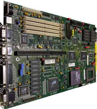
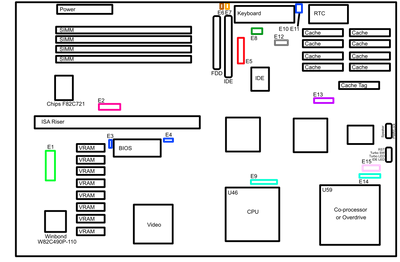
Viglen Jacup 3 (DT-Tornado2) Motherboard (Viglen Executive DX33)
---------------------------------------------------------------------------------------------------------------------------------------
Intel Processor running at 80486SX, 80486DX, 80486DX2 and 80486DX4 Overdrive with built in voltage regulator
Overdrive socket.
ISA Sockets on a riser card.
4 SIMM sockets for memory expansion up to 64Mb using 36 bit 72 pin 70ns SIMMS.
64k Cache supplied as standard, upgradable to 256K Cache. (256k required if upgrading past 8Mb).
Two 16550 UART compatible 9 pin serial connectors.
One 25 pin printer port.
AT style keyboard.
PS/2 style mouse.
One floppy disk controller.
One IDE hard disk controller supporting upto 540Mb of Hard Disk Drive space.
S3 VGA 86C805 Onboard Graphic Chip, with 1Mb memory upgradable to 2Mb
Viglen Part Code: PM30X100.
Connections
-------------------------------------------------------------------------------------------------------------------------------------
Keylock Connector J14
This connects to the lock on the front panel, so that the keyboard can be disabled with a key.
Power L.E.D. Connector J14
This connects to the front panel to display the power status of the motherboard.
Speaker Connector J14
This goes to a speaker for the sound output.
Turbo L.E.D. Connector J15
This goes to the turbo LED on the front panel, which lights up when the computer is running in high speed (turbo) mode.
Turbo Switch Connector J15
This goes to the turbo button on the front panel. When this button is pressed in the computer is running in high speed (turbo) mode.
Reset Switch Connector J15
When this switch is pushed it will cause the computer to do a hard reboot.
Hard Disk L.E.D. Connector J15
This goes to the Hard Disk L.E.D. on the front panel, which lights up when the IDE Hard Disk is in use.
--------------------------------------------------------------------------------------------------------------------------------------
Jumper Settings
VGA Configuration - Jumper E1 (Shown in Green)
--------------------------------------------------------------------------------------------------------------------------------------
Function Jumper E1
VGA 2-3 5-6 Closed Enable VGA
Enable/Disable 2-3 Open 4-5 Closed Disable VGA
T3/T2 Cycle 1-4 Closed T3 LDEV# sampling
1-4 Open T2 LDEV# sampling
TTL/3-State 8-9 Closed TTL LEDV# level
Level Signal 7-8 Closed 3-State LDEV# level
DAC/System/Local Bus Access 11-12 Closed DAC System Bus Access
10-11 Closed DAC Local Bus Access
VRAM Size 14-15 17-18 Closed 2Mb VRAM
14-15 16-17 Closed 1Mb VRAM
13-14 16-17 Closed 512Kb VRAM
Extension Monitor Identification 19-20 Closed or 20-21 Closed
VGA Mode Jumper E1 Refresh Rates
640 x 480 25-26 23-24 Closed 60Hz Non-Interlaced
25-26 22-23 Closed 72Hz Non-Interlaced
800 x 600 25-26 23-24 Closed 60Hz Non-Interlaced
25-26 22-23 Closed 72Hz Non-Interlaced
26-27 22-23 Closed 56Hz Non-Interlaced
1024 x 768 23-24 26-27 Closed 43Hz Interlaced
25-26 23-24 Closed 60Hz Non-Interlaced
25-26 22-23 Closed 72Hz Non-Interlaced
1280 x 1024 23-24 26-27 Closed 43Hz interlaced
Super I/O Shunt - Jumper E2 (Shown in Pink)
---------------------------------------------------------------------------------------------------------------------------------------
C & T I/O Chip
Enable 1-2 Open
Disable 1-2 Closed
IRQ Select (731 only)
IRQ 5 3-5 Closed
IRQ 7 5-7 Closed
Type of I/O Chip
C & T 721 4-6 Closed
C & T 731 6-8 Closed
DMA Channel Select (731 only)
DRQ 6 9-11 Closed
DRQ 7 11-13 Closed
DMA ACK Select (731 only)
DACK 6 10-12 Closed
DACK7 12-14 Closed
Eprom/Flash Eprom Shunt - Jumper E3, E4, E10 & E11 (Shown in Blue)
E3 E4 E10 E11 Function
1-2 Closed 1 Meg Eprom/Flash Eprom
2-3 Closed 2 Meg Eprom/Flash Eprom
1-2 1-2 1-2 Closed Read Only
2-3 2-3 2-3 Closed Read/Write Mode
Local Bus IDE Configuration - Jumper E5 (Shown in Red)
----------------------------------------------------------------------------------------------------------------------------------------
Function Jumper E5
Enable Local-BUS IDE 3-5 Closed
Disable Local-BUS IDE 1-3 Closed
I/O Addr. 0B4H, 0B8H, 0BCH 2-4 Closed ADI2 Register Port Address
I/O Addr. 034H, 038H, 03CH 4-6 Closed ADI2 Register Port Address
486XX CPU 9-11 8-10 Closed Host CPU Mode
Reserved 7-9 10-12 Closed Host CPU Mode
Drive ID 30H 13-15 14-16 Closed Drive ID Selection
Drive ID 31H 13-15 16-18 Closed Drive ID Selection
Drive ID 32H 15-17 14-16 Closed Drive ID Selection
Drive ID 33H 15-17 16-18 Closed Drive ID Selection
Mouse Port - Jumper E6 (Shown in Brown)
Mouse Port Jumper E6
Disable Open
Enable 1-2 Close
CMOS RAM Shunt - Jumper E7 (Shown in Orange)
CMOS CLR Jumper E7
Normal Open
Clear 1-2 Closed
Colour/Mono Shunt - Jumper E8 (Shown in Dark Green)
Jumper E8
Mono 3-4 Closed
Colour 5-6 Closed
CPU Mode Shunt - Jumper E9 and E14 (Shown in Turquoise)
----------------------------------------------------------------------------------------------------------------------------------------
Socket U46 Socket U59 Jumper E9 Jumper E14
486SX None 2-3 Only 1-2 3-4 5-6
486DX/DX2 None 1-2 3-4 5-6 1-2 3-4 5-6
486SX 487SX 7-8 Only 2-3 Only
486SX/DX & 486DX2 ODPR486DX (1 - socket type) 8-9 Only 1-2 3-4 6-7
486SX/DX & 486DX2 ODP486 (2 - socket type) 7-8 Only 1-2 3-4 5-6
486SX/DX & 486DX2 Pentium ODP (1 - socket type) 8-9 Only 1-2 3-4 6-7
486SX/DX & 486DX2 Pentium ODP (2 - socket type) 7-8 Only 1-2 3-4 5-6
None ODP486DX (1 - socket type) 8-9 Only 1-2 3-4 6-7
None ODP486DX (2- socket type) 7-8 Only 1-2 3-4 5-6
None Pentium ODP (1 - socket type) 8-9 Only 1-2 3-4 6-7
None Pentium ODP (2 - socket type) 7-8 Only 1-2 3-4 5-6
System Clock Shunt (installed in U52) - Jumper E12 (Shown in Grey)
CPU Frequency Crystal Frequency Jumper E12
20 MHz 40 MHz 3-4 5-6 Closed
25 MHz 50 MHz 1-2 Closed
33 MHz 66 MHz 1-2 5-6 Closed
40 MHz 80 MHz 1-2 3-4 Closed
50 MHz 50 MHz 1-2 Closed
Cache - Jumper E13 (Shown in Purple)
Cache Jumper E13
---------------------------------------------------------------------------------------------------------------------------------------------
0K All Open
64K 3-5 4-6 Closed
256K 1-3 2-4 7-8 9-10 11-12 Closed
Chipset Mode Shunt - Jumper E15 (Shown in Light Pink)
Function 1-2 3-4 5-6 7-8 9-10
Un-sync ready Close Open
Sync ready Open Close
Ext rdy Enable Close
Ext rdy Disable Open
Cache
Burst 3-2-2-2 Close
Burst 2-1-1-1 Open
0 Waitstate Close
1 Waitstate Open