VOGONS


VRM for Shuttle HOT-541 motherboard?

Topic actions

First post, by vmr_

User metadata
Rank Member
Rank
Member

Just noticed my Shuttle HOT-541 socket 7 mobo has a slot for VRM.

Any ideas how VRM module looks like, and what is the benefit of having it? Is it required for any type of CPU supported by this motherboard?

Did not test the motherboard yet, I assume it works without the VRM module?

Thanks

Attachments

Retro builds & sandbox
IBM XT 5160 | 286 | 386 | 486 | S4 SI5PI AIO & S4 Batman + P60 SX828
S8 & PPro 200 | SS7 FW 5VGF & Asus P5A & AOpen AX59PRO K6-III+ 550MHz
Asus K7M Athlon 1Ghz GDF | Abit SH6 Pentium III 1GHz SL4KL...

Reply 1 of 27, by Deksor

User metadata
Rank l33t
Rank
l33t

The VRM is required to run split voltage CPUs. This includes Intel Pentium MMX, AMD K6(-[2/3]), Cyrix 6x86L/MX and Cyrix MII

It'll run a regular pentium perfectly fine.

Trying to identify old hardware ? Visit The retro web - Project's thread The Retro Web project - a stason.org/TH99 alternative

Reply 2 of 27, by vmr_

User metadata
Rank Member
Rank
Member
Deksor wrote on 2021-03-01, 22:47:

The VRM is required to run split voltage CPUs. This includes Intel Pentium MMX, AMD K6(-[2/3]), Cyrix 6x86L/MX and Cyrix MII

It'll run a regular pentium perfectly fine.

What about Cyrix M1? Will it run without VRM?

Retro builds & sandbox
IBM XT 5160 | 286 | 386 | 486 | S4 SI5PI AIO & S4 Batman + P60 SX828
S8 & PPro 200 | SS7 FW 5VGF & Asus P5A & AOpen AX59PRO K6-III+ 550MHz
Asus K7M Athlon 1Ghz GDF | Abit SH6 Pentium III 1GHz SL4KL...

Reply 4 of 27, by vmr_

User metadata
Rank Member
Rank
Member
Deksor wrote on 2021-03-01, 22:50:

Isn't that the Cyrix 6x86 ? ^^
Yes it'll run without a VRM.

Hurray, one step closer to build my first Cyrix retro machine.

Retro builds & sandbox
IBM XT 5160 | 286 | 386 | 486 | S4 SI5PI AIO & S4 Batman + P60 SX828
S8 & PPro 200 | SS7 FW 5VGF & Asus P5A & AOpen AX59PRO K6-III+ 550MHz
Asus K7M Athlon 1Ghz GDF | Abit SH6 Pentium III 1GHz SL4KL...

Reply 5 of 27, by Deksor

User metadata
Rank l33t
Rank
l33t

Thanks for making that photo by the way. I added it here http://www.win3x.org/uh19/motherboard/show/4448

Trying to identify old hardware ? Visit The retro web - Project's thread The Retro Web project - a stason.org/TH99 alternative

Reply 6 of 27, by vmr_

User metadata
Rank Member
Rank
Member
Deksor wrote on 2021-03-01, 23:01:

Thanks for making that photo by the way. I added it here http://www.win3x.org/uh19/motherboard/show/4448

Cool, can do a few more for some other mobos, will check what's there. Nice resource for mobos documentation.

Retro builds & sandbox
IBM XT 5160 | 286 | 386 | 486 | S4 SI5PI AIO & S4 Batman + P60 SX828
S8 & PPro 200 | SS7 FW 5VGF & Asus P5A & AOpen AX59PRO K6-III+ 550MHz
Asus K7M Athlon 1Ghz GDF | Abit SH6 Pentium III 1GHz SL4KL...

Reply 7 of 27, by Deksor

User metadata
Rank l33t
Rank
l33t

Sure ! please do. Even if there's already a photo, if the quality of the present photo is bad or if the board in the picture is slightly different, please make one 😀

Trying to identify old hardware ? Visit The retro web - Project's thread The Retro Web project - a stason.org/TH99 alternative

Reply 8 of 27, by Horun

User metadata
Rank l33t++
Rank
l33t++

On some boards with VRM socket you have to use a VRM dummy or short some pins inside or else the cpu does not get the 3.3 volts on all proper pins.
Have a Micron board like that. The dummy looks like the picture (is a DEC version but works same) but all it does it short certain pins so the 3.3 v/3.45v from onboard reg flows thru.
If the CPU is not dual voltage (like MMX) and uses only 3.3, 3.45, etc then you should short these pins with standard jumpers IF the the board does not boot up.
Pin 4A VIO core to Pin 5A 3.3, Pin 4B VIO to 5B 3.3 core
Pin 6A 3.3 to Pin 7A Vcc core, Pin 6B 3.3 to Pin 7B Vcc core
Originally taken from Intel design guideline in my notes. Let me double check but am fairly sure that is correct.
Maybe some else can double check my pins ?
edit: got the pins # wrong....

Attachments

  • Filename
    Pentium VRM design.pdf
    File size
    531.65 KiB
    Downloads
    59 downloads
    File license
    Public domain
  • VRM dummy.jpg
    Filename
    VRM dummy.jpg
    File size
    254.22 KiB
    Views
    1067 views
    File license
    Public domain
Last edited by Horun on 2021-03-02, 23:24. Edited 1 time in total.

Hate posting a reply and then have to edit it because it made no sense 😁 First computer was an IBM 3270 workstation with CGA monitor. Stuff: https://archive.org/details/@horun

Reply 9 of 27, by vmr_

User metadata
Rank Member
Rank
Member
Horun wrote on 2021-03-02, 03:42:
On some boards with VRM socket you have to use a VRM dummy or short some pins inside or else the cpu does not get the 3.3 volts […]
Show full quote

On some boards with VRM socket you have to use a VRM dummy or short some pins inside or else the cpu does not get the 3.3 volts on all proper pins.
Have a Micron board like that. The dummy looks like the picture (is a DEC version but works same) but all it does it short certain pins so the 3.3 v/3.45v from onboard reg flows thru.
If the CPU is not dual voltage (like MMX) and uses only 3.3, 3.45, etc then you should short these pins with standard jumpers IF the the board does not boot up.
Pin 10A Vcc core to Pin 11A VSS, Pin 10B VSS to Pin 11B VCC core
Pin 12A Vcc core to Pin 13A Vcc core, Pin 12B VSS to Pin 13B Vcc core
Originally taken from Intel VRM 8.2 design guideline in my notes. Let me double check but am fairly sure that is correct.
Maybe some else can double check my pins ?

Thanks - I will attepmt to start the mobo as-is, as I recall buying it as a working one a few years ago 😀

If it doesn't boot, will take the advice on board 😀

Last edited by vmr_ on 2021-03-02, 14:59. Edited 1 time in total.

Retro builds & sandbox
IBM XT 5160 | 286 | 386 | 486 | S4 SI5PI AIO & S4 Batman + P60 SX828
S8 & PPro 200 | SS7 FW 5VGF & Asus P5A & AOpen AX59PRO K6-III+ 550MHz
Asus K7M Athlon 1Ghz GDF | Abit SH6 Pentium III 1GHz SL4KL...

Reply 10 of 27, by majestyk

User metadata
Rank Oldbie
Rank
Oldbie

It won´t work if you´re using any dual voltage CPU and probably also with other CPUs depending on the CPU´s internal wiring.
You need to set these 2 jumpers:

vrm_jump1.jpg
Filename
vrm_jump1.jpg
File size
165.24 KiB
Views
1023 views
File license
Fair use/fair dealing exception

As per default the jumpers are set whenever there´s no VRM present.

Reply 11 of 27, by Deksor

User metadata
Rank l33t
Rank
l33t

Does anyone know what connector these VRMs use ? They should be pretty easy to clone these days (and potentially we could make better ones that could power K6-2+ or tilamook pentium mmx)

Trying to identify old hardware ? Visit The retro web - Project's thread The Retro Web project - a stason.org/TH99 alternative

Reply 12 of 27, by majestyk

User metadata
Rank Oldbie
Rank
Oldbie

It´s just a regular 30 pin connector with 2.54mm pitch as used for IDE or floppy connectors.

The whole assembly with the two bolts and retentions is not available anymore, but it´s not necsessary for a working VRM.
Back in the days most Pentium VRMs provided just 2.8 and 2.9V.
Today we could make some highly efficient step-down regulator with DIP-switches for all the common core voltages.

Reply 13 of 27, by Deksor

User metadata
Rank l33t
Rank
l33t

Yeah exactly. I have zero knowledge about how to do that though. Best I could do would be a clone.

Trying to identify old hardware ? Visit The retro web - Project's thread The Retro Web project - a stason.org/TH99 alternative

Reply 14 of 27, by Horun

User metadata
Rank l33t++
Rank
l33t++

I errored earlier: is my Intel Advanced ATX (Thor) board that needs the jumpers or shorting VRM even to use a 3.3v regular pentium.

Attachments

Hate posting a reply and then have to edit it because it made no sense 😁 First computer was an IBM 3270 workstation with CGA monitor. Stuff: https://archive.org/details/@horun

Reply 15 of 27, by PC Hoarder Patrol

User metadata
Rank l33t
Rank
l33t

Bit more info from archive.org

https://web.archive.org/web/19980210141740/ht … /VRM.HTM#HD0217

The image links are missing, but if you copy the image location & search the url list for the file names you'll still find them

Also, a quote from the shuttle.eu archive

"HOT-1051 Voltage Regulator Module (VMR)
also called SRM-1051
- Can be used for the mainboard types: HOT-541, HOT-553
- Controller type: linear
- to support CPUs with high current or / and
double voltage (dual voltage: 2.8V from the VRM and 3.3V from the mainboard)
- The plug-in socket is on the mainboard next to the CPU socket
- For the correct setting of the jumpers, please refer to the supplementary sheet.
- Intel Pentium CPU P55C (MMX) 166 MHz is supported,
The clocked VRM module HOT-106 is required for the 200 MHz variant.

Note: The earlier version HOT-105 supplies 2.5V with jumper position "B".
Originally, dual-voltage CPUs were announced with this voltage.
"

Reply 16 of 27, by vmr_

User metadata
Rank Member
Rank
Member

Thank you all for initial guidance. A bit of progress done today, after some not do promising results from 2 days ago.

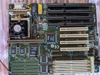
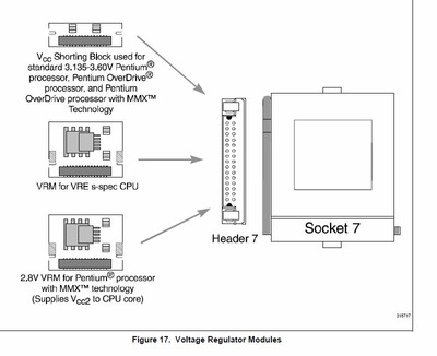
Motherboard came with a 100mhz Intel Pentium CPU, and all jumpers were set as per first photo.

Added first 2 stocks of EDO RAM I find in a drawer, a PCI common video card and... no joy. No video output, no beeps, nothing.

After a few more tries involving swapping slots, cards, EDO RAM sticks - all still as per first setup, same results.

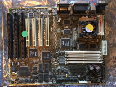
Now today I went for a trusted Tseng ISA video card, and for a fourth pair of EDO RAM (as I used it in a p60 Hendrix setup). Result? It's alive! Pic below.

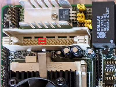
Forgot to mention, no VRM shortcuts were needed, but it also works with the 2 jumpers as suggested by majestyk.

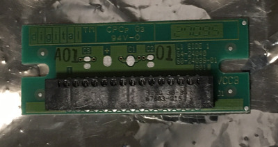
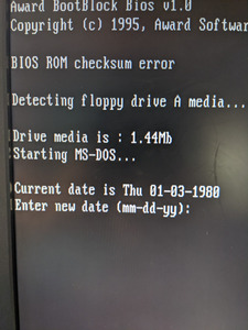
I reckon the Dallas RTC module is gone (the built-in battery), so this messes up things and cannot seem to be able to access BIOS settings.

System looks for floppy, and happily boots from it. Does not see the standard 514mb HDD drive usually detected by default by boards from same period, so more tinkering required.

Any suggestions on steps to access BIOS? Is RTC modding/ replacement the only option?

Attachments

Retro builds & sandbox
IBM XT 5160 | 286 | 386 | 486 | S4 SI5PI AIO & S4 Batman + P60 SX828
S8 & PPro 200 | SS7 FW 5VGF & Asus P5A & AOpen AX59PRO K6-III+ 550MHz
Asus K7M Athlon 1Ghz GDF | Abit SH6 Pentium III 1GHz SL4KL...

Reply 17 of 27, by Deksor

User metadata
Rank l33t
Rank
l33t

It looks like the BIOS rom is corrupted. This is the recovery setup. The dallas may or may not be dead. It's the BIOS rom that have a problem like this screen says 😀 (if it was the dallas, it'd say CMOS ram checksum error or something like that)

You can find bioses for this board here (not sure which one is the right one, read the readme.txt) https://download.shuttle.eu/Archive_2004/BIOS/541/ . Put it on a floppy disk and then flash the bios.

Now the fact the ROM might have corrupted itself may mean that it's about to die so maybe the BIOS flashing won't solve the issue. If that's the case, you can try to flash a new ROM (or maybe someone tried to update the bios and failed leading to this situation).

Trying to identify old hardware ? Visit The retro web - Project's thread The Retro Web project - a stason.org/TH99 alternative

Reply 18 of 27, by vmr_

User metadata
Rank Member
Rank
Member

Any advice on where to find replacement new ROM?

Retro builds & sandbox
IBM XT 5160 | 286 | 386 | 486 | S4 SI5PI AIO & S4 Batman + P60 SX828
S8 & PPro 200 | SS7 FW 5VGF & Asus P5A & AOpen AX59PRO K6-III+ 550MHz
Asus K7M Athlon 1Ghz GDF | Abit SH6 Pentium III 1GHz SL4KL...