Sphere478 wrote on 2024-04-09, 17:11:
Never bypass pullups/pulldowns like that if what was done is what I think was done. There is an example of someone doing this in the tillamook thread, I had to fix the procedure for them 🤣. Anyway, following their method it sometimes blows up a resistor.
Ah, I'd wondered if there might be a problem using boards that actually used the REGE pin, relieved it's just blowing a resistor. Must be quite a low value resistor for it to blow?
Sphere478 wrote:
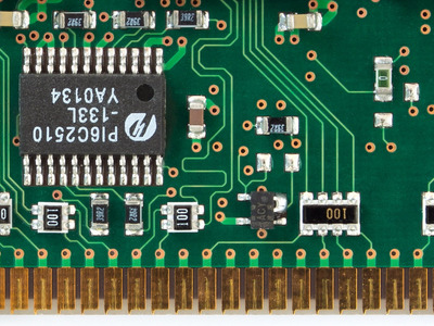
I would have to look at this circuit closer to see what exactly is going on, but snufkin, could a smd resistor replace that solder blob?
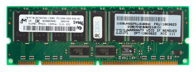
Maybe, but it'll start to matter what value is used. A quick recap: On my Micron stick then there's already a 10k pull up on the input to the inverter, so that if nothing drives REGE (pin 147) then the output from the inverter will be low, so the stick will be registered. I removed the inverter and used two pads provided nearby to bypass the inverter. That means the 10k pull up is connected to the LE pin on the register chip, putting it in transparent mode. If a motherboard tries to drive the pin high then nothing happens. If a motherboard tries to drive the pin low then a current of around .33mA will flow. So nothing should break, but does mean the stick operates back-to-front: if the board tries to set the stick to registered then the stick will be unregistered. So there's a good chance that the stick won't work in a board that actually supports switching from registered to unregistered.
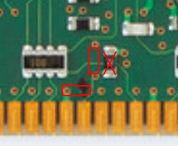
So, if the inverter isn't removed then the problem becomes how to neatly have the input to the inverter be default low, but without becoming a risk to the motherboard. That can either be done by lifting one end of the existing 10k pull up and connecting it to a convenient GND (I think that's what I'd do now). Or add a pull down resistor to the input that's strong enough to overcome the 10k pull up so that the input is still read as low.
The datasheet for the register chip on the Micron stick says that for a 2.5V input then an input must be under 0.7V. So I'll aim for 0.5V on a 3.3V supply. That'd mean a 2.8V (3.3V - 0.5V) drop over the existing 10k resistor, which would be .28mA. So if a pull-down was 1.79k then the input voltage would be 0.5V ( 0.5V / .28mA = 1.786kohm ). Using a smaller resistor will pull the input closer to GND, but also increase the current to a few mA (~3mA) if REGE is ever driven high.
Short version... Adding a 1k resistor between the input pin and GND should make the stick default to unregistered and keep the stick working as expected if the motherboard tries to drive REGE either high or low. Still not guaranteed to work in a motherboard that supports registered because a motherboard might rely on the stick default being registered, so could just leave REGE floating and expect that to set the stick to registered.
RayeR wrote on 2024-04-09, 20:37:
UPDATE: there are 2 "T" structures, each on one side. Both contains 0-ohm resistor...
That sounds right. Rotating both 0-ohm resistors seems to pick 3 different settings, I think for clock phase, one of which will give you the best timings. Clock signal comes in on one link, through a via, I think to a loop on an internal layer, through a via to the other side of the stick, through the second link, and back to the clock feedback. I'm assuming each of the 3 positions has a different internal loop length.