Just in case anyone finds this if searching for a similar problem in the future, a couple of things:
1) Hi.
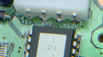
2) Turns out it was simple, although perhaps not obvious. Check the 12V on the top of the molex power connector.
I assumed that if a through hole pin had connections on both sides that it would have a plated through hole via. The 12V solder joint on the bottom side was fine, so I figured it would be connected on the top side as well, but it wasn't.
Once I realised that, I soldered the top of the leg on to the track, reassembled the drive and it now at least opens and closes correctly, and the drive head seeks. Haven't yet fully tested it, but it's looking hopeful.
Bit of a trek getting there, so I thought I note down what I found just in case it's of use.
It really helped having a second working drive to compare against. I started out checking IC3, which is an AN8388SR 4ch motor drive (disc spin, head worm drive, focus, tracking). I thought maybe something had happened to Vref (pin 14), which looks like it controls which way the outputs get driven. But both the good and bad drive had that pin with ~3k ohms to Gnd and 2.6V when just the PCB was powered (all the motor outputs disconnected). The resistance to Gnd for all the pins (only measured on the 20k scale on my meter) was about the same on the two boards.
Pin 1 - PVcc - 12k
Pin 2 - PGnd1 - 0
Pin 3-10 - Motor outputs - >20k
Pin 11 - PGnd2 - 0
Pin 12 - PVcc2 - 0k2
Pin 13 - SVcc - 18k
Pin 14 - Vref - 3k
Pin 15&16 - Input 4&3 - >20k
Pin 17 - OpAmp+ - 11k
Pin 18 - OpAmp- - 15k
Pin 19 - OpAmpOut - 17k
Pin 20 - Gnd - 0
Pin 21-24 - Input 2, PCut2, Input1, PCut1 - >20k
So nothing seemed particularly broken there. Voltages on the good boards were:
1 - 9V
2-6,8,10&11,20 - 0V
7 - 0.8V
9 - .9V
12 - 5.2V (my PSU 5V seems a little high)
13 - 12V
14-19,21,23 - 2.5V
22,24 - 5V
On the bad board I finally found some differences.
3 - 9V
5 - 3.5V
7 - 4.8V
9 - 3.8V (those are all the motor outputs, so being driven all the time)
22,24 - 0V
Notice that pin 13 (SVcc) is at 12V on both good and bad boards, getting power from the underside of the Molex.
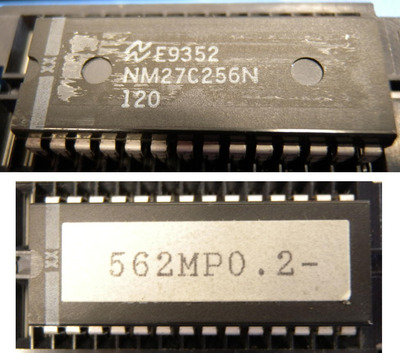
The thing there was pins 22 and 24 both being 0V rather than 5V. Tracing those back, one went to IC2 pin 23 (MN662710RA signal processor) and one went to IC6 pin 44 (MN1882410X00, a MN1880 microcontroller). I was getting the wrong output from two different chips, so I guessed the problem was further up the line. I saw a message from elsewhere where someone with a different problem suggested that the EEPROM may have been corrupted. So I checked the contents of the two EEPROMs and they look to be the same. Just in case, I put the EEPROM from the known good board in to the duff one, and it behaved the same. So the problem wasn't the EEPROM. If I remember I'll edit this message later and add the contents.
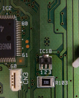
So I started hunting around, and eventually found IC18 (transistor of some sort?). On the good board that was ~18k to Gnd, but was >200k on the bad board. That pin goes back to the 12V on the top side of the Molex, via a 33r resistor. So I soldered the joint, applied power, and got the correct voltages on the motor drive inputs and outputs. As it was now apparently working, I didn't trace it forward to find out what had been missing its 12V. A question for another time.
Fingers crossed I now have two working CR562 again. Fairly high nostalgia level with this drive in particular as it was my first ever CD drive.
[Edit to add EERPOM file]
[Also to note that the drive was working, then suddenly started clicking again, so I suspect my solder joint hasn't made good contact to the track. Will have to remove the connector to check out the pad, might need a wire mod]