VOGONS


First post, by Macsbig

User metadata
Rank Newbie
Rank
Newbie

Hi all,

First time poster, so first - hello to everyone!
I have recently got the retro PC bug again and bought lots of goodies. I have been a PC builder and occasional gamer since the late 90s (my first PC was a TIME Colossus Cyrix 6x86mmx@200mhz, with a MASSIVE 15" screen!! Haha - yeah, I know, but I didn't know any better back then! 😉 ).

Anyway, on to my problem,
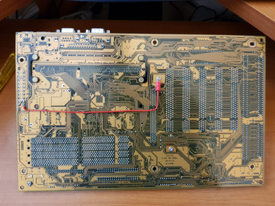
One board I have recently bought is a Gigabyte GA-6BXE REV 1.9, which, sadly, I have found out during research, isn't really up to running a decent GPU Board (REV 2.0 on is much better?), as I understand it has a low Current limit on the AGP trace, but I would like to put in a Riva TNT or a Voodoo 3 3000 AGP (I had this card back in the day from new and loved it, - my first expensive upgrade purchase, so it has a special place in my heart!). I can't really stretch to another board so have explored how I can get over this. I already have these cards so would like to utilize them. Furthermore, I understand there is a Motherboard mod' to link ATX pins 1,2 and 11 straight to the AGP VRM pad with a decent gauge wire?

First off, have many of you here tried this, and if so has it been successful?

Secondly, would you guys recommend the mod', does it come with hidden consequences?

Thirdly, would the fact that the board wouldn't be original any more detract from its desirability?

Thanks for reading, and for any replies I may receive.

Mark

Reply 1 of 33, by Doornkaat

User metadata
Rank l33t
Rank
l33t

Hey and welcome to the forum! 😀

The problem with those boards isn't traces, it's an underpowered linear voltage regulator that can't handle the currents some AGP cards from 1999 and onward demand.

I haven't tried the mod myself but Gigabyte incorporated it into later designs by adding two Voodoo3 jumpers to some of their later revision boards like Rev. 2.0 of your board. Setting the jumpers bypasses the transistor and feeds the AGP slot +3.3V directly from the ATX connector.
The only hidden consequence of this is possibly a bit more ripple on +3.3V and less protection against overcurrent from your PSU. With a good PSU it shouldn't matter.

Realistically due to its standard features and especially its problems with later AGP cards the board isn't that much of a desireable 440BX board to begin with. (Not shitting on your board here, it's still a good foundation for a capable Win9x machine!) The mod on the other hand is period correct and reversible.
I wouldn't worry too much about depreciating the board with this mod if it's a clean job. 😀

Reply 2 of 33, by Macsbig

User metadata
Rank Newbie
Rank
Newbie

Thanks, for the reply!

If the underlying problem is with the VRM, then would it be possible (and more desirable) to replace the VRM with a higher throughput item, rather than the (sort of) ugly link across the back of the board?

Reply 3 of 33, by Doornkaat

User metadata
Rank l33t
Rank
l33t
Macsbig wrote on 2021-04-05, 14:28:

Thanks, for the reply!

If the underlying problem is with the VRM, then would it be possible (and more desirable) to replace the VRM with a higher throughput item, rather than the (sort of) ugly link across the back of the board?

In theory I guess so, but if it was that easy Gigabyte would have probably just used that approach in their later revisions instead of adding the Voodoo3 jumpers. They might even have recalled the existing boards for rework instead of suffering the PR disaster that ensued.
I believe the problem is probably also related to the heat generated by the transistor.
All in all I'd say it's both more efficient and effective to just add the bodge wire to the back.

Reply 5 of 33, by Doornkaat

User metadata
Rank l33t
Rank
l33t

You're welcome! 😀
If you currently have the system disassembled you may want to contribute to Ultimate Hardware 2019 by posting a good picture for them to add. http://www.win3x.org/uh19/motherboard/show/2782
You can also post the picture here and I'll message Deksor so he can add the picture.
Also what transistor is used on your board? I'm still not certain wether the transistor didn't have enough current capacity or if it simply overheated because it was placed so inconveniently.

Edit: Here's also a good picture of where to solder. NOPE! WRONG TRANSISTOR! I wouldn't even think it's necessary to connect all three +3.3V pins on the ATX connector. One is most likely all you need. This would make the mod look a bit cleaner.

Last edited by Doornkaat on 2021-04-08, 18:43. Edited 1 time in total.

Reply 7 of 33, by Macsbig

User metadata
Rank Newbie
Rank
Newbie
Doornkaat wrote on 2021-04-05, 15:20:
You're welcome! :-) If you currently have the system disassembled you may want to contribute to Ultimate Hardware 2019 by postin […]
Show full quote

You're welcome! 😀
If you currently have the system disassembled you may want to contribute to Ultimate Hardware 2019 by posting a good picture for them to add. http://www.win3x.org/uh19/motherboard/show/2782
You can also post the picture here and I'll message Deksor so he can add the picture.
Also what transistor is used on your board? I'm still not certain wether the transistor didn't have enough current capacity or if it simply overheated because it was placed so inconveniently.

Edit: Here's also a good picture of where to solder. I wouldn't even think it's necessary to connect all three +3.3V pins on the ATX connector. One is most likely all you need. This would make the mod look a bit cleaner.

I'm still collecting the some of the pieces, maybe I will just chuck it in a circa 2005 case just to try it all. Perhaps i'll take some pics then 😀
I'll also have a chat to one of the Sparkies I work with, to see what he thinks too, about just coming off the one pin. Not sure how the PSU is constructed, but maybe multiple pins helps smooth out the Volts, IDK? But your deffo right, would look a lot tidier!

Reply 8 of 33, by Macsbig

User metadata
Rank Newbie
Rank
Newbie
BigDaddyM wrote on 2021-04-05, 16:06:

I have this board in 1.9 revision and few days ago I paired it with Voodoo3 2000 with no issues. Fast and stable

Interesting! Not sure what Wattage the V3 2000 pulls, but be careful you don't overheat your Mobo. I've heard you can fry the card and/or the Mobo. What CPU are you running with that?

Reply 10 of 33, by Macsbig

User metadata
Rank Newbie
Rank
Newbie
BigDaddyM wrote on 2021-04-05, 17:52:

According to this page Voodoo3 2000 has 10W TDP. I used covington celeron 300 but I don't remember if I ovorclocked it to 450 MHz 😀

http://hw-museum.cz/vga/39/3dfx-voodoo3-2000-agp-rev--c2

Haha, nice!
I've got both a 400 and 450 p2, not sure what I'll use yet.

I'm considering designing and making my own heatsink for the 3000, as I've heard they run very hot.

I'm thinking about making a full size one to cover the GPU and memory modules from a machined block of solid Aluminium. Or maybe split it into 3 pieces. I'll make it so it has a fan mount too. 😀

Reply 14 of 33, by Doornkaat

User metadata
Rank l33t
Rank
l33t
BigDaddyM wrote on 2021-04-05, 16:06:

I have this board in 1.9 revision and few days ago I paired it with Voodoo3 2000 with no issues. Fast and stable

Back then you could also read very mixed experiences with those boards and more demanding AGP cards. Some were fine even with GeForce cards, others reported artifacting and crashes with only Riva TNT2 M64 cards.
If I'm right in assuming the transistor converts +5V to +3.3V it will get pretty hot. It is located at an awkward point that restricts convection and airflow. There's no heatsink on it and it has only got a small copper plane to act as a substitute heatsink. For longevity I would recommend active airflow over the transistor even if things are currently fine.
If the transistor fails it'll likely short and pass +5V right to the AGP card. This will most likely damage any AGP card you're running on it.

Reply 16 of 33, by Macsbig

User metadata
Rank Newbie
Rank
Newbie

Hi again,

Right, I did the mod and the Mobo didn't boot, fans ran but no beeps or video. After checking everything and everything seeming OK I finally removed the mod...and Voilà we have boot again! Now, the odd thing is if I check the voltage on the VRM I get 5v in, control signal is .24v, but output is 1.5v! This is obviously wrong.

Strange thing is the TNT 3.3v card I'm using to boot is working - I'm confused, but it would explain why it refuses to boot when the pin 1,1&11 are connected to the VRM! Are there any Electrical wizards here who could help 🙁

Anyone have any ideas?

Regards

Reply 18 of 33, by Macsbig

User metadata
Rank Newbie
Rank
Newbie
Doornkaat wrote on 2021-04-07, 17:20:

Could you show us pics of where you soldered?

Looks all OK to me, but as I said I've removed the links now. In the BIOS VGTL is showing 1.5 - I'm assuming that's AGP voltage?

Attachments

Reply 19 of 33, by Doornkaat

User metadata
Rank l33t
Rank
l33t

That's 100% the hotfix that Gigabyte supposedly inofficially suggested.
What's also weird is imho that the PBC has discolorations at the other transistor but not the one supposedly responsible for +3.3V on AGP.
Could it be the transistor is supposed to only generate 1.5V and the other one is responsible for 3.3V?
Could you try starting the board and measuring voltages of both transistors at the back?

Edit: Reding the comments here this seems to be the case. The linked picture is wrong. I'll edit that post.