Reply 20 of 33, by Macsbig
Doornkaat wrote on 2021-04-08, 18:40:That's 100% the hotfix that Gigabyte supposedly inofficially suggested. What's also weird is imho that the PBC has discoloration […]
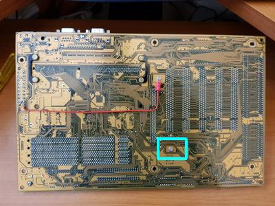
That's 100% the hotfix that Gigabyte supposedly inofficially suggested.
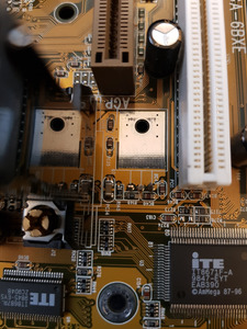
What's also weird is imho that the PBC has discolorations at the other transistor but not the one supposedly responsible for +3.3V on AGP.
Could it be the transistor is supposed to only generate 1.5V and the other one is responsible for 3.3V?
Could you try starting the board and measuring voltages of both transistors at the back?Edit: Reding the comments here this seems to be the case. The linked picture is wrong. I'll edit that post.
Interesting.
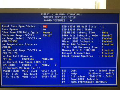
What I have now tried is removing the LDO module, and connecting as the picture shows. I now have 3.3v in the bios VGTL (as you'd expect).
You are right though, I noticed the "other" LDO module was getting warm when the board was in bios mode (I have this board just on a desk nothing attached bar the video card), but the LDO in question was not. I found this odd, as I was obviously drawing power from the AGP bus (the luke warm LDO module) and even though nothing was in the PCI slots (I assumed this was what the "warm"module was supplying) this was getting warmer.
With no modded connection, and no LDO module connected (removed) I still had approx 0.5 volt there.
I would like to get to the bottom of this, ideally replacing the underpowered LDO module with something of the correct Current rating (7A?)
But as of now things seem on the face of it, better.
Just as an aside, I've noticed if I connect the PC speaker of have constant high/low beeping, indicating a CPU issue. But it boots into bios OK. In hardware monitoring the -12 line is showing -62.3...Odd! EDIT!! The beeping goes away with an older PSU with a -5v(white) line, and shows the correct -5v in the Bios, so I'm assuming this Mobo doesn't like "newer" PSU's)!!
Also I can only set the FSB to 66mhz to boot. 100 gets the fans running but nothing more.
I'm really not sure what the 1.5v line would be used for though?
To be continued!