VOGONS


First post, by waterbeesje

User metadata
Rank Oldbie
Rank
Oldbie

Hi everyone,

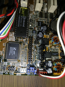
I've had this Asus P5A-B board for a while, but never took too much time to tinker with it. Recently I've bought an at case to give it shelter and I'm setting up the board.
Currently it's running a Pentium 200 MMX at 95x3 or 100x2,5 and 2,9v.

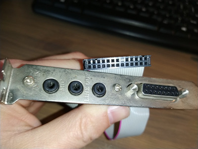
In my stuff I found a mir/usb riser that works perfectly, and I found some random audio riser that works well with the PC chips M577. However, the m577 riser has the wrong pin blocked for my P5A-B. Drilling the blocked pin is easy, but I'm not convinced it would work as expected: I'm wondering if the pinout would be different.

Any of you have an idea? Does anybody have the pinout for the motherboard?

If the pinout does not match my riser, I'm going to rework the connections to make them match, so that's no problem for me.

Attachments

Stuck at 10MHz...

Reply 1 of 4, by Deksor

User metadata
Rank l33t
Rank
l33t

I think the first thing to check are the ground pins.
If you can find where they are, this should prevent you from blowing up anything (unless the game port has 5 and 12v outputs which I doubt)

Trying to identify old hardware ? Visit The retro web - Project's thread The Retro Web project - a stason.org/TH99 alternative

Reply 2 of 4, by waterbeesje

User metadata
Rank Oldbie
Rank
Oldbie

I've got some measurements. Just used my multimeter ohm beeping setting (generally safe as it's putting only 2,5v on it)

Pin 25 is clearly not connected (as the pin is not there)

Pin 7 + 9 + 19 +21 +23 are gnd.
Pin 15 is directly connected to +5v

Does this give you any clue?

Stuck at 10MHz...

Reply 3 of 4, by weedeewee

User metadata
Rank l33t
Rank
l33t
waterbeesje wrote on 2021-04-12, 21:22:
I've got some measurements. Just used my multimeter ohm beeping setting (generally safe as it's putting only 2,5v on it) […]
Show full quote

I've got some measurements. Just used my multimeter ohm beeping setting (generally safe as it's putting only 2,5v on it)

Pin 25 is clearly not connected (as the pin is not there)

Pin 7 + 9 + 19 +21 +23 are gnd.
Pin 15 is directly connected to +5v

Does this give you any clue?

Nope it gives me no clue whatsoever 😀

but given this ftp://ftp.alsa-project.org/pub/manuals/cmi/8330-spec.pdf

you might be able to figure out which pin of the connector goes to which pin on the cmi8330 and figure out the pinout that way.
(pin list is on the last pages)
though, do take into account that there might be a resistor or capacitor on the lines.

Right to repair is fundamental. You own it, you're allowed to fix it.
How To Ask Questions The Smart Way
Do not ask Why !
https://www.vogonswiki.com/index.php/Serial_port