VOGONS


First post, by Khalil86

User metadata
Rank Newbie
Rank
Newbie

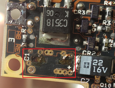
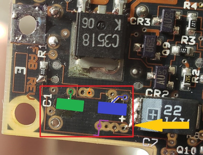
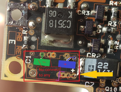
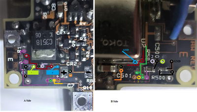
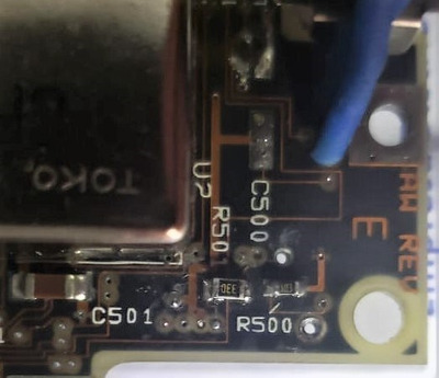
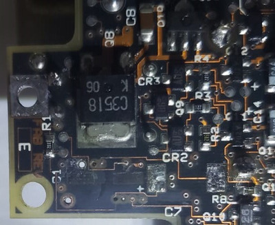
Hello everybody, i´m trying to repair a compaq LTE/286, the capacitors melted some tracks and roads in the motherboard in the two faces and i can't find a technical diagram of ther motherboard to wire it back.

Somebody has the motherboard schematics diagram?

Attachments

  • Mother mio2.jpg
    Filename
    Mother mio2.jpg
    File size
    198.96 KiB
    Views
    281 views
    File license
    Public domain

Reply 1 of 6, by Doornkaat

User metadata
Rank l33t
Rank
l33t

From the picture it looks like this is pretty straightforward. Unless I simply don't understand what happened. That's always a possibility as well. 😅

The missing pads from the capacitor seem to connect directly to the vias next to them.

The one trace that melted at the lower boarder or the red square can be traced in the solder mask. It's just a few mm missing so no big deal.

Am I missing something?

Reply 2 of 6, by Doornkaat

User metadata
Rank l33t
Rank
l33t

Colored in the different places where to rework/replace pads/traces.
Also clean up the solder where the yellow arrow points.
Not too sure wether the orange via needs to be reconnected to the trace. Likely it's fine and just looks funny in the picture.

I hope this helps! 😀

Oh, and welcome to the forum btw! 😀

Attachments

  • Mother mio2.jpg
    Filename
    Mother mio2.jpg
    File size
    197.29 KiB
    Views
    263 views
    File license
    Fair use/fair dealing exception

Reply 3 of 6, by pentiumspeed

User metadata
Rank l33t
Rank
l33t

Also there are tracks and vias destroyed as well, Check these all to be sure with meter and jumper them.

I had LTE 286 before. Nice cute thing but biggest drawback is LCD based on CGA, not VGA and hard to see. So sold it and got LTE 386s/20 which was nice too, also sold later on.

Cheers,

Great Northern aka Canada.

Reply 4 of 6, by Khalil86

User metadata
Rank Newbie
Rank
Newbie

Thank you all very much for your answers.
The problem seems simple when you see it at first, but when you start to measure continuity things get complicated.
The circles that I mark that I calculate are the vias in some cases end up there without connecting to anything in the case of the capacitor the negative pad does not connect with the negative of the motehrboard or with anything else, the paths that are cut I bridged them but I still have those places that I don't know where layers that are in the middle of the plate would be connected to other connections and that is what I lack.

Sorry for my English

Attachments

  • Mother 2.png
    Filename
    Mother 2.png
    File size
    225.15 KiB
    Views
    233 views
    File license
    Public domain

Reply 6 of 6, by Khalil86

User metadata
Rank Newbie
Rank
Newbie

I tried to mark more or less what I found and put symbols of ? in everything that does not connect or I do not find what it connects with.

Attachments

  • todo.png
    Filename
    todo.png
    File size
    579.33 KiB
    Views
    219 views
    File license
    Public domain
  • Lado B-1.jpg
    Filename
    Lado B-1.jpg
    File size
    36.66 KiB
    Views
    222 views
    File license
    Public domain
  • Lado A-1.jpg
    Filename
    Lado A-1.jpg
    File size
    60.39 KiB
    Views
    222 views
    File license
    Public domain