VOGONS


ABIT BH6, is it dead?

Topic actions

Reply 40 of 59, by Doornkaat

User metadata
Rank l33t
Rank
l33t

That's an inductor, from the looks of it it's used in the VCC line on one of the PS/2 ports to reduce noise.
It failing would cause the PS/2 port to not work but shouldn't cause any more problems (assuming it didn't do significant damage to the PCB).
I wonder why it failed before the fuse though.

Reply 41 of 59, by snufkin

User metadata
Rank Oldbie
Rank
Oldbie

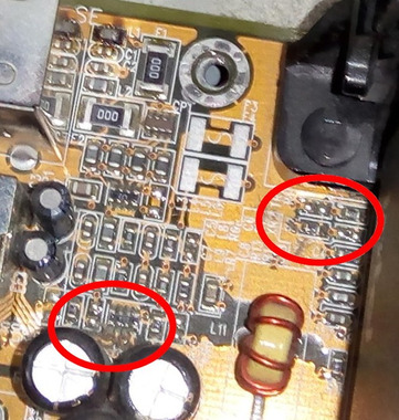
Well, it looks like L1 definitely smoked, but that doesn't say anything about why it smoked. If this is fixable then I expect it's now a soldering iron job. There are a couple of other patches in the area that look to me like either dirt or corrosion, which I've marked. Konc mentioned that this board is known to have bad caps, and I've had some that leaked without bulging. I know it'll take some time, but get the board out of the case again and give it a good inspection under a good light. If you've only got metal surfaces around then put the motherboard on something insulating that doesn't hold static very well (cardboard box, wooden chopping board, couple of pieces of paper (watch no pins poke through to the metal surface). Might at this point be worth removing everything (CPU, RAM), powering up and measuring some voltages, particularly around L1 and the big CPU caps.

Attachments

  • BH6_componentChecl.jpg
    Filename
    BH6_componentChecl.jpg
    File size
    120.48 KiB
    Views
    780 views
    File license
    Fair use/fair dealing exception

Reply 42 of 59, by retrogamerguy1997

User metadata
Rank Member
Rank
Member

I finally found some cardboard I could rest the motherboard on and powered it on and fans run but no beep codes. I did check the area for debris but only after blowing air on it and getting something in my eye but I couldn't see anything or find any leakage.

Reply 43 of 59, by weedeewee

User metadata
Rank l33t
Rank
l33t
Doornkaat wrote on 2021-05-15, 13:54:

That's an inductor, from the looks of it it's used in the VCC line on one of the PS/2 ports to reduce noise.
It failing would cause the PS/2 port to not work but shouldn't cause any more problems (assuming it didn't do significant damage to the PCB).
I wonder why it failed before the fuse though.

probably because the "fuse" is a zero ohm resistor and not really a fuse 😁

Right to repair is fundamental. You own it, you're allowed to fix it.
How To Ask Questions The Smart Way
Do not ask Why !
https://www.vogonswiki.com/index.php/Serial_port

Reply 44 of 59, by Doornkaat

User metadata
Rank l33t
Rank
l33t
weedeewee wrote on 2021-05-15, 16:30:
Doornkaat wrote on 2021-05-15, 13:54:

That's an inductor, from the looks of it it's used in the VCC line on one of the PS/2 ports to reduce noise.
It failing would cause the PS/2 port to not work but shouldn't cause any more problems (assuming it didn't do significant damage to the PCB).
I wonder why it failed before the fuse though.

probably because the "fuse" is a zero ohm resistor and not really a fuse 😁

Well, I have to admit, reading the text on some parts helps from time to time.😅

Reply 45 of 59, by snufkin

User metadata
Rank Oldbie
Rank
Oldbie
Doornkaat wrote on 2021-05-15, 16:59:
weedeewee wrote on 2021-05-15, 16:30:
Doornkaat wrote on 2021-05-15, 13:54:

That's an inductor, from the looks of it it's used in the VCC line on one of the PS/2 ports to reduce noise.
It failing would cause the PS/2 port to not work but shouldn't cause any more problems (assuming it didn't do significant damage to the PCB).
I wonder why it failed before the fuse though.

probably because the "fuse" is a zero ohm resistor and not really a fuse 😁

Well, I have to admit, reading the text on some parts helps from time to time.😅

It might be a sort of fuse. It'll have about 20 mohm resistance and I'd guess around .75W maximum power dissipation, gets us (I think) about 20A at failure. Although a no-fun datasheet say to limit to 7A. I think that means that even after the board has caught fire, at least the fuse will still be ok.

At the moment, I'm thinking the problem is a voltage regulation one and it might just be coincidence that problems started to crop up after flashing the bios.

Reply 46 of 59, by digger

User metadata
Rank Oldbie
Rank
Oldbie

As several others here have already mentioned, this particular model suffered from bad caps. It was released during the "capacitor plague" around the turn of the Millennium.

I remember it well, since I worked as a sales rep at a computer store when this board was released. Right up until the release of the BH6, Abit had a reputation for making rock-solid products. That reputation was destroyed almost overnight with the release of the BH6. Even within the warranty period, the return rate of those boards was crazy high. At a certain point, Abit even sent a technician to the store to solder new caps on the returned boards by hand, on the assembly workbench in the back of our store! 😮 This was the only time we ever experienced something crazy like that, instead of the regular RMA procedure. (Sending it back to the manufacturer or importer.)

One customer (who up until that point had been very loyal to us) was outraged when he learned that he would be getting back the same board that he brought in under warranty, repaired like that. He insisted on getting a new board instead, but there was a strict policy of not replacing the boards, but having the visiting Abit guy replace the caps in store.

My guess is that this was some kind of agreement between Abit and the computer stores selling their products. Considering the crazy high failure rate, replacing all the failed boards for brand-new (and problem-free) ones would probably have been too costly for Abit. But this in-store repair service must not have been cheap either.

The visiting technician likely didn't replace all caps on each board, because he had a huge stack of boards waiting for him when he arrived at our store . And he probably had many other stores to visit as well, each with similar stacks of defective boards. So my guess is that he probably only replaced the caps that were the most prone to premature failures (within the warranty period). So frankly I wouldn't be surprised if many of the repaired boards would have started to fail again eventually.

I sympathize with that angry customer. I wouldn't have trusted that board either. But we were instructed not to swap the boards in his computer. 😕

Abit used to be right up there with Asus when it came to being considered a premium quality motherboard manufacturer. But those unreliable counterfeit capacitors really did them in. And the sad thing is that apart from the capacitors, the BP6 was a perfectly fine motherboard, as far as I remember.

Seriously, replace all the caps in that thing, regardless of how pristine they look.

Reply 47 of 59, by retrogamerguy1997

User metadata
Rank Member
Rank
Member

I don't have a soldering iron and have no skills in that area.

I still have yet to try a new battery and testing power with a multimeter, neither of which I've been able to get my hands on (yet)

Reply 48 of 59, by digger

User metadata
Rank Oldbie
Rank
Oldbie
retrogamerguy1997 wrote on 2021-05-15, 18:26:

I don't have a soldering iron and have no skills in that area.

Call Abit. Ask them to send over one of those technicians. 😄

Reply 49 of 59, by darry

User metadata
Rank l33t++
Rank
l33t++
digger wrote on 2021-05-15, 18:40:
retrogamerguy1997 wrote on 2021-05-15, 18:26:

I don't have a soldering iron and have no skills in that area.

Call Abit. Ask them to send over one of those technicians. 😄

That was "a bit" funny .

Seriously, though, I would no trust myself to re-cap a multi-layer board myself either, yet . If OP has no interest and/or skills in soldering himself, I see 2 options :
a) buying another still working board and paying somebody to recap it
b) paying somebody to try to repair and likely recap the current one (may be more expensive than it is worth)

One, obviously not local to OP, option to get the work done is https://www.badcaps.net/index.php (not an endorsement as I have never dealt with them).

If a given motherboard was built using caps that are known to be prone to failure (BH6 was known to have that issue nearly 20 years ago and the flow of time certainly has not helped anything), recapping ( and potential repairs due to collateral effects of failed caps ) will eventually be necessary, likely sooner than later . Doing this as pro-actively as possible is, IMHO, the beast and least expensive course of action in the long term : these boards are getting rarer and more expensive and working/undamaged ones will become even rarer as time marches on and their crappy factory installed caps continue to degrade .

Reply 50 of 59, by PcBytes

User metadata
Rank Oldbie
Rank
Oldbie

Badcaps dot net were known to do great jobs, especially when it came about ABIT boards. They were also the guys from where I've learnt about bad caps and have already saved a nice Soyo 6BA+IV from meeting the same fate that quite many of the ABIT boards did. OP can go ahead safely and ask to get the board recapped.

Speaking of ABIT boards, I do hope that one day I will land myself on any of the 440BX boards they made. I would just LOVE recapping one of those and then pushing it to the maximum possible.

"Enter at your own peril, past the bolted door..."
Main PC: i5 3470, GB B75M-D3H, 16GB RAM, 2x1TB
98SE : P3 650, Soyo SY-6BA+IV, 384MB RAM, 80GB

Reply 51 of 59, by retrogamerguy1997

User metadata
Rank Member
Rank
Member

yikes that repair service is almost $200. And the ebay prices for Abit BH6 boards isn't much better being $90+

EDIT: got my hands on a replacement battery and yeah same result. later I'm going to see if there is a power issue but I'm not sure which pins all need to be tested nor do I know how to use a multimeter.

Reply 52 of 59, by darry

User metadata
Rank l33t++
Rank
l33t++
retrogamerguy1997 wrote on 2021-05-15, 21:15:

yikes that repair service is almost $200. And the ebay prices for Abit BH6 boards isn't much better being $90+

I agree that the amount is significant, but unless you are dead set on a BH6, you do have other options .

For example, high end Asus boards (P2B family and P3B-F) from the same era typically still used quality caps . I use an Asus P3B-F with Japanese capacitors (forgot the brand) and have no issues personally (nor do I recall reading about capacitor issues with these).

EDIT : Just to be clear, even quality electrolytic capacitors will eventually fail, so re-capping will be inevitable at some point in the future for everything and anything that uses that uses them . Being able to do the job yourself is a useful skill to have, IMHO .

Reply 53 of 59, by retrogamerguy1997

User metadata
Rank Member
Rank
Member
darry wrote on 2021-05-15, 22:40:
I agree that the amount is significant, but unless you are dead set on a BH6, you do have other options . […]
Show full quote
retrogamerguy1997 wrote on 2021-05-15, 21:15:

yikes that repair service is almost $200. And the ebay prices for Abit BH6 boards isn't much better being $90+

I agree that the amount is significant, but unless you are dead set on a BH6, you do have other options .

For example, high end Asus boards (P2B family and P3B-F) from the same era typically still used quality caps . I use an Asus P3B-F with Japanese capacitors (forgot the brand) and have no issues personally (nor do I recall reading about capacitor issues with these).

EDIT : Just to be clear, even quality electrolytic capacitors will eventually fail, so re-capping will be inevitable at some point in the future for everything and anything that uses that uses them . Being able to do the job yourself is a useful skill to have, IMHO .

yeah I'm not dead set on a specific board, I just really want to get going again. i almost considered buying a thin client but the ones that are listed on philscomputer lab are either all sold out or the ones that have listings are now way above the price points they were when those videos came out. I don't know if I can get a new slot 1 board for a good price, but I guess if anything I still have an old hp pavilion xe736 as a back up and I can still add in the sound card I bought. I also have a pentium 4 system, but it is too new to really run 98SE and might not even have PC-PCI/SB-link. Well my hp might not have that either. Still fucking sucks that I have a dead motherboard now. and all this started with a soundcard I bought on ebay. Fucking ridiculous.

Reply 54 of 59, by digger

User metadata
Rank Oldbie
Rank
Oldbie

Hey, I was joking with you about calling Abit, but I feel you, man. It sucks to have a computer component fail on you, especially one that is becoming increasingly rare.

I hope you can find someone skilled, friendly and enthusiastic enough who's willing to repair the board for you for a reasonable price (or perhaps just a crate of beer or something), in your neck of the woods.

Doesn't Ben Heck live in Wisconsin too? He definitely has the skills for this. 😉

Reply 55 of 59, by shamino

User metadata
Rank l33t
Rank
l33t

Slot-1 contacts are flaky. Since you're getting no beep codes, a contact problem with the CPU is one of the possibilities, and that happens a lot with Slot-1.
The CPU retaining bracket can impede being able to easily reseat the CPU. In some cases it actually prevents seating the CPU fully into the slot.
I would remove the CPU retaining bracket from the board so that it's out of the way. Then it will be a lot easier to keep reseating the CPU until it shows some sign that the CPU is actually running. Also look close in the slot and at the CPU contacts for anything that needs to be cleaned/removed.
Personally I don't like to use those retaining brackets unless I'm going to turn it vertical and get permanent with the installation. At this stage you're very much in the "fiddling" mode, so I'd leave the bracket out for now.
I know you reseated it earlier but it might need more persistence to rule out that issue.

I don't know this board but if it has FSB jumpers, set them to 66MHz. That will make it easier to POST so you have a better chance of getting somewhere with the troubleshooting. For the same reason, also minimize the components that are plugged in. Don't start adding things or increasing the FSB setting unless and until it starts to behave.

I'm a big believer in checking voltages, as snufkin suggested. If you can get your hands on a multimeter, it would be informative to check various voltages.

In order to get beep codes you need good power, motherboard, CPU, and BIOS. You don't need RAM, video, or keyboard.
If you decide to hone in on getting beep codes though then be really damn sure that you have a working speaker connection. 😀

Reply 56 of 59, by retrogamerguy1997

User metadata
Rank Member
Rank
Member

the board does not have any FSB jumpers, it's all handled through the BIOS.I don't think contact with cpu was ever the problem seeing as the system ran fine until this whole situation happened.

Reply 57 of 59, by shamino

User metadata
Rank l33t
Rank
l33t

Sorry for the string of quotes, just trying to keep the sequence of events organized:

retrogamerguy1997 wrote on 2021-05-14, 14:58:

So I was told to update my BIOS, which then didn't work and the BIOS was totally borked with no way to enter it and requiring a recovery disk. I was later sent a floppy drive, 2 disks, and one cable. the floppy disks were wiped during transit so I remade the disks myself by putting in the floppy drive in my pentium 4 system and doing it there. So once I did that, I put the floppy drive in the system with the ABIT BH6 motherboard and used the recovery disk to try and reflash the bios again. It failed to do so. It was suggested that the chip might have been faulty but just in case I was told to reseat it. I didn't have a proper chip pulling tool and really had a though time getting it out. But it did come out and then I reseated the chip and made sure it was fully in. After powering on the system again, now all I got was a blank screen and the only activity was the fans spinning. So I was sent another bios chip, one that is known to be working and flashed with the latest bios for the board. Put it in, and still the same thing; fans spin but nothing on screen. I was told to then remove the ram and all the cards and disconnect the drives in hopes that there would be beep codes, but nothing. Fans spin up, but no beep codes. And this is where I've hit a dead end.

snufkin wrote on 2021-05-14, 18:39:

If the socket is through hole, can you check the rear side of the motherboard under the PLCC socket? Or if it's surface mount, a picture with the chip removed. I'm wondering if when the socket cracked it may have damaged a via or surface mount pad.

Just to recap the steps so far:
1) Was working, but couldn't set IRQ in BIOS (HN)

retrogamerguy1997 wrote on 2021-05-14, 18:46:

1) Correct

snufkin wrote on 2021-05-14, 18:39:

2) Flashed BIOS to SS, couldn't enter the BIOS (did anything appear on screen at this point? Any beep codes?)

2) Yeah a message did a appear on the screen, no beep codes

3) Prepared a recovery floppy with the SS BIOS, recovery appeared to take place (disk was read), but no change
4) Removed and reseated chip, after this no display and no beep, just spinning fans.

3) Yeah it just would reboot show the same message, the disk would boot only for the program to fail again. I failed several times before messaging the user here again and that was when I was told to reseat the chip and if that failed he would send me a new one.
4) Correct

5) Replaced chip, no change.

5) Correct

Have you got a multimeter you can use to check the voltages on the pins of the chip holder?

I don't have a multimeter of my own, my dad probably has one for his model train stuff. If he does have one that I can use, how do I test it?

I think you should focus on trying to get back to step 3. You had a display. Something happened when you removed and reseated the original Flash chip.
Unless I missed something, I think the original chip still has the same programming on it that was giving you a garbled display, correct? If so, it should still be able to give you that now. This is a known, versus the other chip which has not been demonstrated to do anything at all with your board (even if it should).

Try removing the chip that's in it, and take a closeup picture into the socket while the chip is removed. Look for any lifted pads or other damage.
If you look close, you might be able to find where the traces are leading that come from the socket. With a multimeter, you could check for continuity from the pins of the socket to those places on the board. Also consider doing the voltage checks that were suggested earlier.
Then install the original chip that was giving you stuff on the screen (*read next paragraph first). Take a picture of the contacts on that chip also. This combination was giving you a garbled display before, so something must have gone wrong here that needs to be found.
After the chip is inserted, do the same continuity test as above but using the actual pins of the chip instead of the socket. The chip should have continuity to everywhere on the motherboard it's supposed to be connecting to.

*Since you don't have a PLCC extractor:
When you put back the original chip, try putting a strong piece of string or fishing line or similar underneath the chip when you install it, so you'll have a safer way to pull it out again if needed. If you put the line across the corners then it won't interfere with any pins. If you don't fully seat the chip it will be easier to pull out (I used to do this for hotflashing in the past). But given the problem you're trying to solve here, I understand you might want to seat it more fully.

Is there any chance you inserted one or the other of the PLCC chips incorrectly? They are keyed on one corner, but with a little effort I think it's possible to put them in wrong, and it would cause electrical damage that could explain the problem. With a cracked socket it's even easier for that to happen.

Extraction can be done using a thin nail, but it's tricky to pry the chip without breaking the socket. A PLCC extractor has a hooked shape so that it gets under the chip better.

==========

Once you have the old BIOS installed that ought to be giving you a display (and probably also beep codes) - if it continues to be black and beepless then reseating the CPU will still need attention. It's been reseated already so the contact it had before when it worked is no longer in effect. The slot-1 interface can be as picky as a Nintendo. If you can remove the slot-1 retaining bracket that makes the CPU easier to reseat fully.

Reply 58 of 59, by retrogamerguy1997

User metadata
Rank Member
Rank
Member
shamino wrote on 2021-05-17, 23:24:

I think you should focus on trying to get back to step 3. You had a display. Something happened when you removed and reseated the original Flash chip.
Unless I missed something, I think the original chip still has the same programming on it that was giving you a garbled display, correct? If so, it should still be able to give you that now. This is a known, versus the other chip which has not been demonstrated to do anything at all with your board (even if it should).

I don't recall saying anything about garbled display. The display was fine until it went dark.

shamino wrote on 2021-05-17, 23:24:

Try removing the chip that's in it, and take a closeup picture into the socket while the chip is removed. Look for any lifted pads or other damage.
If you look close, you might be able to find where the traces are leading that come from the socket. With a multimeter, you could check for continuity from the pins of the socket to those places on the board. Also consider doing the voltage checks that were suggested earlier.

What exactly am I looking for with a multimeter, how do I set it up, and how do I know there is continuity? What is a pad?

shamino wrote on 2021-05-17, 23:24:

Is there any chance you inserted one or the other of the PLCC chips incorrectly? They are keyed on one corner, but with a little effort I think it's possible to put them in wrong, and it would cause electrical damage that could explain the problem. With a cracked socket it's even easier for that to happen.

I'm 100% positive I put it in the right way. I put the chips in the exact way they were at the beginning of all this.

Reply 59 of 59, by snufkin

User metadata
Rank Oldbie
Rank
Oldbie
retrogamerguy1997 wrote on 2021-05-18, 00:50:

What exactly am I looking for with a multimeter, how do I set it up, and how do I know there is continuity? What is a pad?

Apologies in advance if any of this sounds patronising, but I'm not sure what level to start at. It'll help to know a little about what a multimeter is measuring to explain how to use it.

Multimeters come in a few forms, but generally on the front of the multimeter will be a large dial to select what to measure, and roughly what value you expect to see. My meter is split in to 4 general areas (plus a couple of extra ones that I'm ignoring for now), with the symbols looking a bit like: V=, V~, A= and Ω.
V= is DC voltage (DC is Direct Current, and in power supply terms means the voltage stays constant) and is generally what you'd use for measuring voltage on digital circuits.
V~ is AC voltage (AC is Alternating Current, where the supply oscillates back and forth, positive and negative, like a sine wave around a middle point) and is more for mains electrical, things with transformers and analogue stuff (amplifiers).
A= is for DC current, measured in Amperes (Amps). A faff to measure in a built circuit as you have to lift pins so that you can insert the metre in to the circuit.
Ω is for resistance, where the meter can calculate the resistance by applying a small voltage across two points and measuring the current that flows.

So, for example, to check for continuity, or electrical shorts, you'd need to measure resistance. My meter has options of 200, 2000, 20k, 200k and 2000k. Each of those numbers is the maximum resistance that can be measured on that setting. If the resistance is any higher then the meter will just say it's open circuit. A short circuit would be around 0 ohms, so if looking for those I generally set my meter to the '2000' setting (I don't need the extra supposed accuracy of using the 200 setting), put one probe on one point to test, and the other probe on the other point. Wait a second to see if the meter responds (my meter is quite slow), then move on.

From the description of how the meter measures resistance, you can see that this generally can't be done with a board turned on. You don't want the meter introducing new voltage signals to the board (this is a good way to make floppy drive motors spin way too fast...), and the meter reading will be confused by the voltages already on the board. It normally doesn't matter which way around the probes are for measuring resistance.

To measure voltages, select V=. My meter has options of 200m, 2000m, 20, 200, 600. For most PC stuff the voltages will be under 12V, so I generally go with 20V. For voltage, it does matter which way around the probes are. It won't hurt anything to have them the wrong way around, but all the readings will have the wrong polarity (so what should be +5V will read as -5V). First you need to find a convenient Ground point to put the black probe. Motherboard mounting screws, backs of IO connectors can be good choices. I generally just find a spare molex and wedge the probe in one of the ground pins on that (either of the black 2 middle ones). Then hold the red probe on the point you want to measure.

Be careful when measuring voltages. If you're trying to measure a pin on a chip and slip, then you can end up with the probe touching two pins at the same time, shorting them together. If it's only for a moment then it probably won't cause any damage, but it's best to make sure that the red probe is only ever touching one point.

--------------------

So, that now over (and I'm not expert at using a meter, so I'm sure others can correct any bad advice)... On the pins around the eeprom that I asked about before, you should now be able to measure:
1) With the board off, continuity of the Ground pin to Ground. Check there's roughly 0 ohms between a mounting screw hole (or one of the Ground pins on the power connector) and what I marked as the ground.
2) With the board on, voltages on the Vdd (+5V) and Vpp (+12V) pins.

There needs to be 0 ohms (or very close to) resistance to the ground pin and +5V on Vdd, otherwise the chip won't work. I don't know much about the programming of the chip, but there will be times during the programming when Vpp should go to +12V.

Now, if those pins measure ok it doesn't mean the chip and socket are ok, there could be other problems. But generally when troubleshooting it's best to start with the easy to test first. I often forget this and start chasing down complicated possibilities, before later finding it's just a damaged cable.