VOGONS


First post, by cyberluke

User metadata
Rank Member
Rank
Member

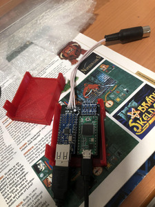
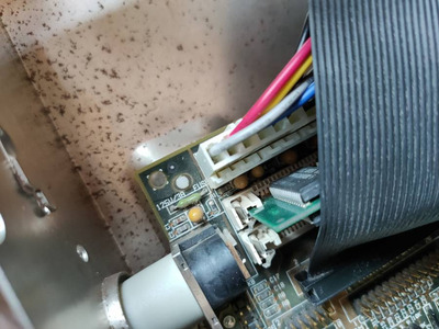
Hi, I was experimenting with Teensy USB to DIN adapter, which has extra 5V USB power from wall adapter. It was working great. But after like 5 restarts, now the motherboard does not recognize any keyboard.

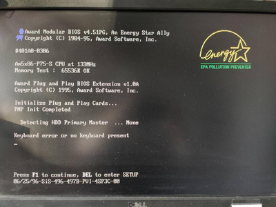
Connecting original AT keyboard results in continuous short burst of PC speaker noise. Like when someone holding a key.

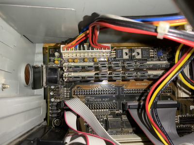
Something wrong with onboard keyboard controller? Some over-voltage problem on DIN port? Is there some solution, please?

Attachments

  • unnamed.jpg
    Filename
    unnamed.jpg
    File size
    1.29 MiB
    Views
    533 views
    File license
    Fair use/fair dealing exception
  • teensy.jpg
    Filename
    teensy.jpg
    File size
    1.39 MiB
    Views
    533 views
    File license
    Fair use/fair dealing exception

Reply 1 of 17, by chrismeyer6

User metadata
Rank l33t
Rank
l33t

Hopefully you didn't overload the keyboard controller on the motherboard and fry it. I would check the keyboard socket for maybe a bad solder connection and check the traces from the keyboard port to the keyboard controller chip for burnt traces or components.

Reply 2 of 17, by cyberluke

User metadata
Rank Member
Rank
Member

Ok, I got response from the maker of this adapter: "To protect the motherboard, a logic level converter (the smallest board) is installed on the adapter board."

"Furthermore, each motherboard has a fuse on the +5 volt line, I recommend checking this fuse.
Your motherboard is kept safe by these two safeguards.
Perhaps due to the high consumption of the keyboard, the fuse needs to be replaced."

So hopefully just fuse problem. I haven't spot any visible issues on the motherboard. I don't think it will be a bad solder connection. This week the machine was running daily.

Reply 3 of 17, by Nexxen

User metadata
Rank Oldbie
Rank
Oldbie

Can you post pictures of the motherboard?
Check on the keyboard V line if it goes to a filter (inductor) and check if it reads 0.06 ohm or higher, if higher it could prevent the correct voltage.
Just a thought.

PC#1 Pentium 233 MMX - 98SE
PC#2 PIII-1Ghz - 98SE/W2K

Reply 4 of 17, by Horun

User metadata
Rank l33t++
Rank
l33t++

As Nexxen said, a picture of the motherboard (or the make and model would be helpful). If no keyboard is connected does the motherboard boot but halt with KB error like it should or does it do something else ?

Hate posting a reply and then have to edit it because it made no sense 😁 First computer was an IBM 3270 workstation with CGA monitor. Stuff: https://archive.org/details/@horun

Reply 5 of 17, by cyberluke

User metadata
Rank Member
Rank
Member
Horun wrote on 2021-06-02, 23:19:

As Nexxen said, a picture of the motherboard (or the make and model would be helpful). If no keyboard is connected does the motherboard boot but halt with KB error like it should or does it do something else ?

Yes, if keyboard not connected, it goes through POST and report KB error.

The board is ASUS 486-PVI-486SP3.

Attachments

  • IMG_0157.jpg
    Filename
    IMG_0157.jpg
    File size
    1.74 MiB
    Views
    476 views
    File license
    Fair use/fair dealing exception

Reply 6 of 17, by Nexxen

User metadata
Rank Oldbie
Rank
Oldbie

NOthing looks blown.
Could you check C1,2,4,17 and 18 if one has a higher resistance than 0.6?

You probably should take out the motherbaord at some point to check continuity between motherboard and keyb port.

PC#1 Pentium 233 MMX - 98SE
PC#2 PIII-1Ghz - 98SE/W2K

Reply 8 of 17, by Nexxen

User metadata
Rank Oldbie
Rank
Oldbie

Maybe check if this applies to your motherboard, maybe you can avoid pulling out the mobo.
https://diagramweb.net/img/ps2-keyboard-to-5- … -diagram-12.gif

PC#1 Pentium 233 MMX - 98SE
PC#2 PIII-1Ghz - 98SE/W2K

Reply 9 of 17, by cyberluke

User metadata
Rank Member
Rank
Member
Nexxen wrote on 2021-06-03, 00:58:

Maybe check if this applies to your motherboard, maybe you can avoid pulling out the mobo.
https://diagramweb.net/img/ps2-keyboard-to-5- … -diagram-12.gif

Funny that it's in Czech language...which is where I am right now. Anyway I have experience with software and Teensy. But this part, I bought on E-Bay. It worked for me with some cheap Genius USB keyboard. And the guy have working video on Youtube plus he is doing PC XT converters like this for a long time. This AT is just something new right now. So based on that, I would trust him, he knows how to connect the pins and shielding. I may raise a question, though.

Reply 10 of 17, by cyberluke

User metadata
Rank Member
Rank
Member

But I should not connect the Teensy to USB 5V. He clarified it is not needed. Which I did not know and the RGB keyboard won't even run without it. So I guess if there is some voltage from PC DIN (I guess 3.3V). Then there is some logic converter 3.3V to 5V. Then there is Teensy USB with additional 5V power line (probably extra), then there might be some problem like current going in from both sides and it might bring 5V to PC DIN under some special condition (like USB device, in this case the keyboard, gets disconnected). Maybe something like reverse polarity and it might blow up the fuse or something else on the board.

Reply 11 of 17, by megatron-uk

User metadata
Rank Oldbie
Rank
Oldbie

Check continuity on the 125v rated green fuse at the top left; it protects the keyboard/keyboard from over-voltage and shorts.

I had similar issues on my identical PVI SP3 ("no keyboard detected", "keyboard failure" - a quick flash of lights on the Kb itself, and then nothing) and it turned out the fuse had blown.

My collection database and technical wiki:
https://www.target-earth.net

Reply 12 of 17, by cyberluke

User metadata
Rank Member
Rank
Member
megatron-uk wrote on 2021-06-03, 07:18:

Check continuity on the 125v rated green fuse at the top left; it protects the keyboard/keyboard from over-voltage and shorts.

I had similar issues on my identical PVI SP3 ("no keyboard detected", "keyboard failure" - a quick flash of lights on the Kb itself, and then nothing) and it turned out the fuse had blown.

Okay, my keyboard does not even light up. I will need to measure it today.

Reply 13 of 17, by megatron-uk

User metadata
Rank Oldbie
Rank
Oldbie

Keyboard error and faulty fuse:

asus_pvi_kb_error.jpg
Filename
asus_pvi_kb_error.jpg
File size
65.26 KiB
Views
412 views
File license
CC-BY-4.0
img20201125134125.jpg
Filename
img20201125134125.jpg
File size
74.84 KiB
Views
412 views
File license
CC-BY-4.0

Removal and replacement of the fuse:

img20201203094706.jpg
Filename
img20201203094706.jpg
File size
52.46 KiB
Views
412 views
File license
CC-BY-4.0
img20201203094756.jpg
Filename
img20201203094756.jpg
File size
53.58 KiB
Views
412 views
File license
CC-BY-4.0

My collection database and technical wiki:
https://www.target-earth.net

Reply 14 of 17, by cyberluke

User metadata
Rank Member
Rank
Member
megatron-uk wrote on 2021-06-03, 09:08:

Keyboard error and faulty fuse:

Yes, that might look like it. Either the fuse or Amikey controller. But how to measure anything on the fuse? Fuse is only for current, you cannot measure any voltage or resistance on fuse, right?

Reply 16 of 17, by megatron-uk

User metadata
Rank Oldbie
Rank
Oldbie

Yes, just check the continuity of the fuse - put your multimeter into continuity mode and (with the computer off!) put one probe to one side of the fuse and the other probe to the other end. It will vary on your model, but on my (ancient) Fluke 75:

IMG20210603110448.jpg
Filename
IMG20210603110448.jpg
File size
213.35 KiB
Views
377 views
File license
CC-BY-4.0

My guess is that there is none, your multimeter will not beep (most models will beep when they show continuity - or at least less than a trivial amount of resistance) or will show open-circuit or similar - ergo it will prove it has blown.

If it doesn't have continuity testing mode, just select resistance and measure it - in that mode it will show infinite resistance if it is blown.

My collection database and technical wiki:
https://www.target-earth.net

Reply 17 of 17, by cyberluke

User metadata
Rank Member
Rank
Member
megatron-uk wrote on 2021-06-03, 10:03:
Yes, just check the continuity of the fuse - put your multimeter into continuity mode and (with the computer off!) put one probe […]
Show full quote

Yes, just check the continuity of the fuse - put your multimeter into continuity mode and (with the computer off!) put one probe to one side of the fuse and the other probe to the other end. It will vary on your model, but on my (ancient) Fluke 75:

IMG20210603110448.jpg

My guess is that there is none, your multimeter will not beep (most models will beep when they show continuity - or at least less than a trivial amount of resistance) or will show open-circuit or similar - ergo it will prove it has blown.

If it doesn't have continuity testing mode, just select resistance and measure it - in that mode it will show infinite resistance if it is blown.

Yeah, I have only this DSO Nano v3. I updated the firmware, so it has some apps to measure voltage and resistance: https://www.seeedstudio.com/DSO-Nano-v3.html ...but normally it is oscilloscope