The subject says it all.
I've found a 5" Canon MD 5501 floppy drive but it comes from Epson PC 486 GR (NEC PC-98 clone). So wondering if it's going to work in an IBM PC.
Thanks in advance!
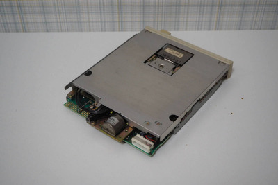
Have you got a photo of the drive and the connectors? There seem to be a few adapters to allow connecting a standard PC floppy drive or Gotek to the PC98, so there's probably some way to connect a PC98 drive to an IBM PC.
Have you got a photo of the drive and the connectors? There seem to be a few adapters to allow connecting a standard PC floppy drive or Gotek to the PC98, so there's probably some way to connect a PC98 drive to an IBM PC.
1(O - Output from motherboard, I - Input to motherboard, pins not listed are GND for both PC98 and IBM)
2Pin   PC98                     IBM PC
32    O Density Select         DenSel
43    I Window?                GND
54    O Head Load              n/c
66    O DS3                    n/c
77    O MFM/FM Select?         GND
88    I Index                  Index
910   O DS0                    MotorA
1011   O Sync?                  GND
1112   O DS1                    DriveSelB
1214   O DS2                    DriveSelA
1316   O Motor On               MotorB
1417   n/c (O Drive Selected)   GND
1518   O Direction              Direction
1620   O Step Pulse             Step
1722   O Write Data             Write Data
1824   O Write Gate             Write Gate
1926   I Track0                 Track0
2028   I Write Protect          Write Protect
2130   I Read Data              Read Data
2232   O Side Select            Side Select
2333   GND (I Disk Change)      GND
2434   I Ready                  Disk Change
I assume the bracketed bits are from different motherboard versions.
So a lot of the signals match up. But a PC98 drive looks like it will have additional outputs on pin 3 (Window, no idea what that's for) and possibly pin 33 (Disk Change) that will be grounded on the IBM PC, which could cause problems, so they ought to be cut. The drive would also be expecting inputs on pin 4 (head load), pin 7 (FM/MFM select), pin 11 (Sync) and possibly pin 17 (Drive Selected), which will all be stuck as GND (except pin 4, which might be floating), which could be a problem if that makes the drive use FM rather than MFM.
The drive might have a jumper somewhere to set the drive number, setting it to DS1 would line up with the Motor On signal, so the drive would be A: if connected after the twist in a floppy cable.
IBM PC wants Disk Change on pin 34, so pin 33 on the drive might need to go to pin 34 on the motherboard.
Depending on how adventurous you feel... you could:
Take a floppy cable and cut 3 and 33.
Check if pin 33 on your drive is shorted to Ground or not (check resistance to pin 31). If not then cut 34 on the cable as well, and connect wire 33 from the drive to wire 34 on the motherboard.
Set the drive to the second drive (DS1)
Plug it in and see what happens...
I have no practical knowledge of the PC98, so it's probably a good idea to wait and see if anyone spots any ways in which this is a really bad idea.
Note for PC with cable twist always set as the second drive, D1 if they count from zero, D2 if counting from 1. Ready and disk change are usually minor problems that result in drive trying to access an empty drive, to determine via the read head whether anything is in there or not before erroring, or missing a disk change so you have to change to another drive (even if it's not there) and back again for it to read the FAT again and go "doh, it's different"
Unicorn herding operations are proceeding, but all the totes of hens teeth and barrels of rocking horse poop give them plenty of hiding spots.
snufkinwrote on 2021-08-11, 21:10:I don't know if it's correct, but I found a pinout for the PC98 internal floppy here: http://radioc.web.fc2.com/column/pc98bas/p […] Show full quote
1(O - Output from motherboard, I - Input to motherboard, pins not listed are GND for both PC98 and IBM)
2Pin   PC98                     IBM PC
32    O Density Select         DenSel
43    I Window?                GND
54    O Head Load              n/c
66    O DS3                    n/c
77    O MFM/FM Select?         GND
88    I Index                  Index
910   O DS0                    MotorA
1011   O Sync?                  GND
1112   O DS1                    DriveSelB
1214   O DS2                    DriveSelA
1316   O Motor On               MotorB
1417   n/c (O Drive Selected)   GND
1518   O Direction              Direction
1620   O Step Pulse             Step
1722   O Write Data             Write Data
1824   O Write Gate             Write Gate
1926   I Track0                 Track0
2028   I Write Protect          Write Protect
2130   I Read Data              Read Data
2232   O Side Select            Side Select
2333   GND (I Disk Change)      GND
2434   I Ready                  Disk Change
I assume the bracketed bits are from different motherboard versions.
So a lot of the signals match up. But a PC98 drive looks like it will have additional outputs on pin 3 (Window, no idea what that's for) and possibly pin 33 (Disk Change) that will be grounded on the IBM PC, which could cause problems, so they ought to be cut. The drive would also be expecting inputs on pin 4 (head load), pin 7 (FM/MFM select), pin 11 (Sync) and possibly pin 17 (Drive Selected), which will all be stuck as GND (except pin 4, which might be floating), which could be a problem if that makes the drive use FM rather than MFM.
The drive might have a jumper somewhere to set the drive number, setting it to DS1 would line up with the Motor On signal, so the drive would be A: if connected after the twist in a floppy cable.
IBM PC wants Disk Change on pin 34, so pin 33 on the drive might need to go to pin 34 on the motherboard.
Depending on how adventurous you feel... you could:
Take a floppy cable and cut 3 and 33.
Check if pin 33 on your drive is shorted to Ground or not (check resistance to pin 31). If not then cut 34 on the cable as well, and connect wire 33 from the drive to wire 34 on the motherboard.
Set the drive to the second drive (DS1)
Plug it in and see what happens...
I have no practical knowledge of the PC98, so it's probably a good idea to wait and see if anyone spots any ways in which this is a really bad idea.
Thanks a lot for such a thorough respond, snufkin. Frankly I don't feel too adventurous, and will probably seek for an easier solution. Yet it's good to have the information on the pinouts here, I'm sure it will be useful.
Thank you for the link, BitWrangler. But I think it refers to a full size Canon MD5501. For some reason both slim and standard drives came under same model number. And the slim in turn had soft button eject and mechanical button eject variations. Let alone versions for Sharp 68K, PC-98 and others.
Here is some info about japanese drives. http://tomoretropc.blogspot.com/2018/07/x680x0-fdd.html
But very little info about IBM PC compatible versions.