So have you got +5 on both DVdd and AVdd now? What does the supply look like? If it's smooth then the inductor value wouldn't be why it doesn't look right.
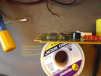
It's possible the MX8315 might have been damaged if the supply voltage was missing. The clock input XI (pin 3) is probably driven directly by the clock generator (I wrongly called it a crystal before). If that was working then it would have been switching at +5V (can you check that?). The inputs on the MX8315 are only allowed to go to 0.5V above Vdd. So it may have had +5V on an input with only 1V on Vdd.
May not actually be a problem if the clock generator is powered with the same 5V supply (after L1) as the MX8315.
[looked up on stackexchange about isolating analog and digital supplies and someone had an Intel reference design which used a .68uH, so 100uH might be a bit high:
https://electronics.stackexchange.com/questio … og-power-supply ]

