VOGONS


First post, by mrzmaster

User metadata
Rank Member
Rank
Member

Hey all, I recently put together a build with these components:

  • Asus TUSL2-C
  • P3 Tuatulin 1.4S
  • New Corsair CX450M PSU
  • Micron 256MB PC133 CL3 x 2
  • GeForce4 Ti 4200

I booted her up for the first time yesterday and got a post no problem, was able to get into the BIOS by hitting del and then the keyboard input froze. I rebooted it and got a post again and a keyboard error. I'm using a USB Das Keyboard with a PS/2 adapter.

Subsequently after the first two post boots, I now no longer can post and no video is displayed on the monitor with a repeating beep tone from the pc speaker. This happens whether the keyboard is connected or not. According to the TUSL2-C manual, this indicates "no DRAM installed or detected". I tried these troubleshooting steps, all of which didn't fix the issue:

  • re-seating the RAM modules and also trying each of them individually
  • swapped out the Ti 4200 for a GF3 and then a Riva TNT2
  • swapped the P3 Tuatulin 1.4S with a 1.0GHz Coppermine
  • removed the CMOS battery and then shorted the CLRTC solder points to try to clear the CMOS (this board doesn't have a jumper)

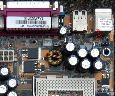
I searched Vogons posts and came up with this thread that suggests removing the C151 chip on the motherboard. I don't know exactly what that is and the link to the Asus forum post in that thread is broken so I wasn't able to get any further information on that. I seem to be stuck right now and it's a bummer because this was supposed to be my new Win98se build. I'm looking for any advice and suggestions on how to fix this problem. Thanks!

Reply 1 of 8, by Eep386

User metadata
Rank Member
Rank
Member

C151 looks like a bussed capacitor, located right behind the PS/2 ports.
I think it's next to the 'CN1' legend on the board.

Attached photo is of a 'straight' TUSL2, but the C151 bussed capacitor should be in the same place:

Attachments

  • Is this C151.png
    Filename
    Is this C151.png
    File size
    1.33 MiB
    Views
    610 views
    File license
    Public domain
Last edited by Eep386 on 2021-10-07, 14:42. Edited 1 time in total.

Life isn't long enough to re-enable every hidden option in every BIOS on every board... 🙁

Reply 2 of 8, by snufkin

User metadata
Rank Oldbie
Rank
Oldbie

Eep386 got here first, but there's a copy of that link on the wayback: https://web.archive.org/web/20180218155846/ht … SLanguage=en-us

Sounds like they're talking about the capacitor network chip marked C151 (150nF maybe?) just behind the PS/2 port, I think part CN1 on the PCB silkscreen. If any of the 4 capacitors in that fails short then the keyboard would stop working. Not sure if it'd cause the other problems though.

Reply 3 of 8, by mrzmaster

User metadata
Rank Member
Rank
Member

Thanks, guys. Before I start forcibly ripping chips off the board, I am still looking for other suggestions. Not to discount the C151 as the cause of the problem, but I would prefer to save that as a drastic last option.

Reply 4 of 8, by snufkin

User metadata
Rank Oldbie
Rank
Oldbie
mrzmaster wrote on 2021-10-07, 15:50:

Thanks, guys. Before I start forcibly ripping chips off the board, I am still looking for other suggestions. Not to discount the C151 as the cause of the problem, but I would prefer to save that as a drastic last option.

Have you got a multimeter? If so, check the resistance between each pair of pins (from one side to the other) on that chip. They might not actually be open circuit, but they should all be some distance away from zero. If any measure near zero (say, under 10 ohms) then there's probably a problem there.

Reply 5 of 8, by Namrok

User metadata
Rank Oldbie
Rank
Oldbie

I see that motherboard has a jumper that changes the voltage supplied to the DRAM, chipset, AGP and PCI. It's 4 pins in a row, and has 3 positions. The middle position is listed as the default in the manual, is 3.40 V, and they strongly recommend you not change it.

What is yours set at? The jumpers look like they are next to the DIMM slots.

Do you have another motherboard you can test the RAM in?

Win95/DOS 7.1 - P233 MMX (@2.5 x 100 FSB), Diamond Viper V330 AGP, SB16 CT2800
Win98 - K6-2+ 500, GF2 MX, SB AWE 64 CT4500, SBLive CT4780
Win98 - Pentium III 1000, GF2 GTS, SBLive CT4760
WinXP - Athlon 64 3200+, GF 7800 GS, Audigy 2 ZS

Reply 6 of 8, by mrzmaster

User metadata
Rank Member
Rank
Member
snufkin wrote on 2021-10-07, 15:55:

Have you got a multimeter? If so, check the resistance between each pair of pins (from one side to the other) on that chip. They might not actually be open circuit, but they should all be some distance away from zero. If any measure near zero (say, under 10 ohms) then there's probably a problem there.

I do not but I can definitely look at picking one up.

Namrok wrote on 2021-10-07, 15:57:

I see that motherboard has a jumper that changes the voltage supplied to the DRAM, chipset, AGP and PCI. It's 4 pins in a row, and has 3 positions. The middle position is listed as the default in the manual, is 3.40 V, and they strongly recommend you not change it.

What is yours set at? The jumpers look like they are next to the DIMM slots.

Do you have another motherboard you can test the RAM in?

It is indeed at the middle position, 3.40V. I actually do have another spare board that I can try the DIMMs in and will give that a shot as well to try to rule them out as the cause. Thanks!

Reply 7 of 8, by mrzmaster

User metadata
Rank Member
Rank
Member

Update: I tested the RAM in another board and it's fine. I then removed the C151 chip per the other thread and it still doesn't post and beeps. I guess the board is dead. 🙁

It's unfortunate because this is the second problematic board in a row that I've dealt with (in one month) for this build. I just had to return a QDI Advance 10T to the seller because it arrived with the heatsink mount clips broken off of the CPU socket.

I'm scouting marketplaces for a suitable S370 board again. Patience is a virtue when it comes to retro builds, I suppose.

Reply 8 of 8, by snufkin

User metadata
Rank Oldbie
Rank
Oldbie

What's your SW1 set to? Could you post a photo of your board? If you get hold of a multimeter it might also be worth checking if the RAM slots have power going to them (measure voltage between the far ends, pin 1 and pin 84). There are a few large capacitors and FETs near the RAM slots that may be involved with supplying power for the RAM. Looks like the board was released in 2001, which was during the dodgy capacitor period, so check to see if any capacitors are bulging slightly, leaning at odd angle (caused by the rubber seals at the bottom blowing out) or have brown crusty stuff coming out the top.