VOGONS


First post, by Rikintosh

User metadata
Rank Member
Rank
Member

Zespodu-a-bez-krytek-s-HDD-Toshiba-T4900CT.jpg

I can boot via floppy, but I need a form of storage that will fit all my games. I would like to hear suggestions for what to do about it.

Take a look at my blog: http://rikintosh.blogspot.com
My Youtube channel: https://www.youtube.com/channel/UCfRUbxkBmEihBEkIK32Hilg

Reply 1 of 16, by Caluser2000

User metadata
Rank l33t
Rank
l33t

Just cut a piece of plastic ice cream container to size and secure it with felcro(hook and loop strips from a $2 shop. Paint to match the rest of vthe system.

There's a glitch in the matrix.
A founding member of the 286 appreciation society.
Apparently 32-bit is dead and nobody likes P4s.
Of course, as always, I'm open to correction...😉

Reply 2 of 16, by waterbeesje

User metadata
Rank Oldbie
Rank
Oldbie

I agree to Caluser2000 for asthetics. Any flat plastic will do.

As for storage, does the computer use normal 44p 2,5"or 40p 3,5" hard disks? the easiest way then is CF with an adapter. Does the computer allow you to manually fill in csh specs or are you stick to a fixed list?

Stuck at 10MHz...

Reply 3 of 16, by Rikintosh

User metadata
Rank Member
Rank
Member

Oops, sorry I forgot to mention, I have the trim cap, the photo is merely illustrative, my big problem is that I don't have the IDE interface that connects the HD to the motherboard, so I can't use a HD on it. It originally uses a traditional IDE 2.5 hd

Take a look at my blog: http://rikintosh.blogspot.com
My Youtube channel: https://www.youtube.com/channel/UCfRUbxkBmEihBEkIK32Hilg

Reply 4 of 16, by Thermalwrong

User metadata
Rank Oldbie
Rank
Oldbie

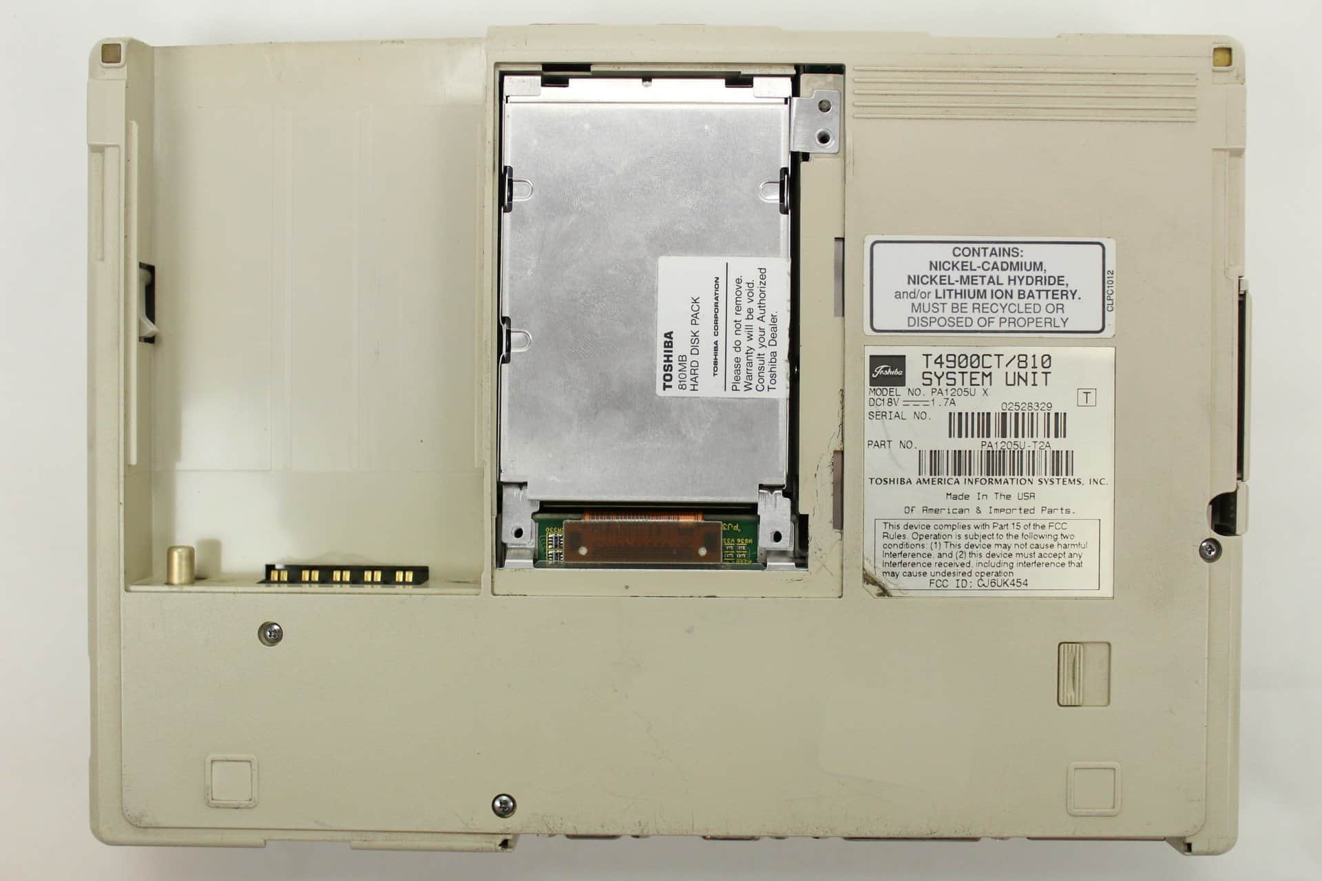
Hey there, I've also got a T4900CT, which thankfully came with a hard drive.

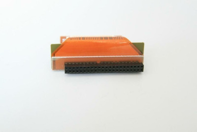
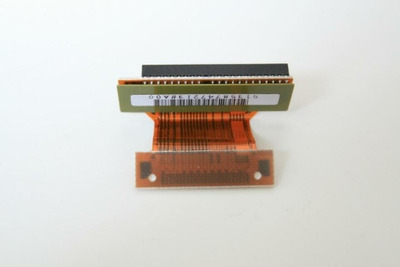
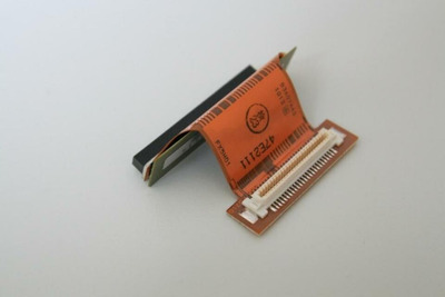
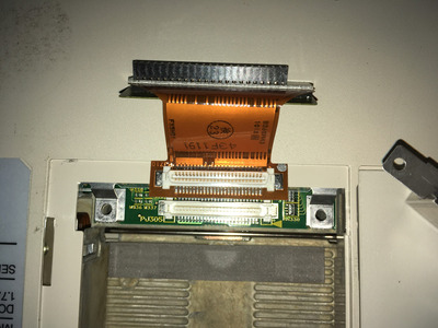
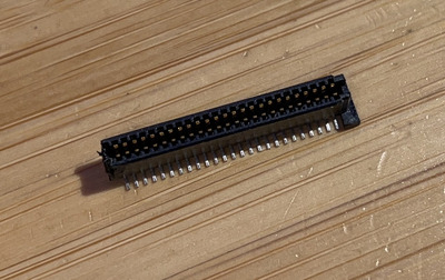
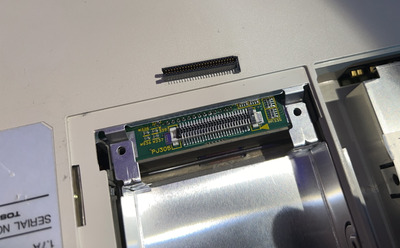
The connector itself is a 1mm pitch, 25-way 2 row connector, with a 1.2mm gap between the pins. The part itself seems a bit unavailable as does that type of PCB connector, but here's what it looks like:

$_593.JPG
Filename
$_593.JPG
File size
15.48 KiB
Views
843 views
File license
CC-BY-4.0
$_592.JPG
Filename
$_592.JPG
File size
21.06 KiB
Views
843 views
File license
CC-BY-4.0
$_59.JPG
Filename
$_59.JPG
File size
22.46 KiB
Views
843 views
File license
CC-BY-4.0

Found from checking my connector and doing a search for "Toshiba PCB FX5HD1 P000199390 Satellite 4900CT HDD" but those pictures may fall offline soon so they're attached here.

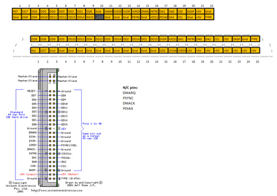
The maintenance manual says this connector has 60 pins? Well that's wrong 🙁 so maybe we can't just check the maintenance manual - I could help with finding the pinout, but then how to sort the PCB > PCB connector? I'm thinking some 3d printed holder for 2x 1mm spaced FPC cables, going to a custom PCB with the HDD pins on it.

Reply 5 of 16, by Rikintosh

User metadata
Rank Member
Rank
Member

I think the only alternative for me would be to solder wire to wire in a female IDE connector

Take a look at my blog: http://rikintosh.blogspot.com
My Youtube channel: https://www.youtube.com/channel/UCfRUbxkBmEihBEkIK32Hilg

Reply 6 of 16, by Thermalwrong

User metadata
Rank Oldbie
Rank
Oldbie

That would be the quick way, another would be to use a 1mm pitch connector like this one, with a PCB or flat flex PCB: https://www.toby.co.uk/board-to-board-pcb-con … -125-03-F-DV-A/

Direct soldering is do-able, though not fun to solder: Re: What retro activity did you get up to today?
I suppose there's not much demand for the IDE connectors on these things to make it really worth designing up a PCB.

But I'll need to beep out the pins of each connector to determine which pin goes where, I'll try to do that after work today 😀

Reply 7 of 16, by Rikintosh

User metadata
Rank Member
Rank
Member

I have some old motherboards that have turned to scrap, which I can remove the IDE connector, which I think will be annoying, is that on the toshiba motherboard, the soldering points are small and very close to each other, I think this will take a few weeks to get ready

Take a look at my blog: http://rikintosh.blogspot.com
My Youtube channel: https://www.youtube.com/channel/UCfRUbxkBmEihBEkIK32Hilg

Reply 8 of 16, by Thermalwrong

User metadata
Rank Oldbie
Rank
Oldbie

Yeah 1mm pitch is too fine for me to solder, especially with that many connections close together. Another option though - is to buy some 1mm pitch Flat Flex Cable (ffc). You can find them if you search for 1mm ffc on thebay, they're usually quite cheap and you can get 26 wire cables quite easily. There's only one seller that sells 25 wire cables.
You can use a pair of those to solder the FFC onto the edges of the IDE connector without removing it. That then lets you run the ribbon cables further off in the hard drive and because they're aware from the connector and fixed at each end, it should be easier to solder.

Reply 9 of 16, by Thermalwrong

User metadata
Rank Oldbie
Rank
Oldbie

Well this was an experience, compared to resoldering that MBC laptop's IDE cable, lots of the pins on this cable are re-arranged:

Silver paint dot is pin 1 technically, though my derivation of the pinout doesn't use specific pin numbers. Also - Today I learned that my Toshiba T4900CT CAN NOT do DMA, it doesn't have the pins for it on the connector, wow!

IMG_1449 (Custom).JPG
Filename
IMG_1449 (Custom).JPG
File size
1.16 MiB
Views
757 views
File license
CC-BY-4.0
2021-11-02 20_31_46-Book1 - Excel.png
Filename
2021-11-02 20_31_46-Book1 - Excel.png
File size
28.34 KiB
Views
757 views
File license
CC-BY-4.0

Reply 10 of 16, by Thermalwrong

User metadata
Rank Oldbie
Rank
Oldbie

Oh also, I have my suspicions from the other recent Toshiba HDD connector thread that maybe the connector is from 3M, the PK10-050P-R-DA or PK10 series in general are a close fit. Checking the datasheet vs my connector, the central part is 1mm on the PK10 and 1.2mm on my part, so. not sure...

Reply 11 of 16, by Rikintosh

User metadata
Rank Member
Rank
Member

Just on idea, but I could design a board and print to pcbway, so all I would have to do is solder a 90 degree ide connector, and the supposed PK10-050P-R-DA connector to the board. I don't understand anything about these boards, but I believe it's something so simple, that maybe I can do. I believe I just need to know what the pinout of the toshiba board is

Take a look at my blog: http://rikintosh.blogspot.com
My Youtube channel: https://www.youtube.com/channel/UCfRUbxkBmEihBEkIK32Hilg

Reply 12 of 16, by Thermalwrong

User metadata
Rank Oldbie
Rank
Oldbie

I am now relatively sure from checking the dimensions that this is a Kyocera 5078 connector: https://www.yumpu.com/en/document/view/365434 … nector-products

Here's the full dimensions:

Filename
Kyocera-5078-69814.pdf
File size
624.03 KiB
Downloads
28 downloads
File comment
5078
File license
CC-BY-4.0

It's the receptacle rather than the plug, so the full part code should be: 24 5078 050 100 861
It does not seem to be available anywhere, it's possible that although it's called Kyocera now, it could've been called AVX or Elco in the past?.

This is pretty cool, now I might know who made all the really fine pitch connectors for lots of Toshiba, Sony and IBM laptops from that era.

Reply 13 of 16, by Rikintosh

User metadata
Rank Member
Rank
Member
Thermalwrong wrote on 2022-02-12, 23:56:
I am now relatively sure from checking the dimensions that this is a Kyocera 5078 connector: https://www.yumpu.com/en/document/v […]
Show full quote

I am now relatively sure from checking the dimensions that this is a Kyocera 5078 connector: https://www.yumpu.com/en/document/view/365434 … nector-products

Here's the full dimensions: Kyocera-5078-69814.pdf

It's the receptacle rather than the plug, so the full part code should be: 24 5078 050 100 861
It does not seem to be available anywhere, it's possible that although it's called Kyocera now, it could've been called AVX or Elco in the past?.

This is pretty cool, now I might know who made all the really fine pitch connectors for lots of Toshiba, Sony and IBM laptops from that era.

I haven't checked yet, but I found a very similar connector on a sony vaio laptop (actually it's the interface that connects a tv capture card), when I have time, I'll check to see if it fits and if the number of connections and their positions align with the connector present on the toshiba

Take a look at my blog: http://rikintosh.blogspot.com
My Youtube channel: https://www.youtube.com/channel/UCfRUbxkBmEihBEkIK32Hilg

Reply 14 of 16, by Thermalwrong

User metadata
Rank Oldbie
Rank
Oldbie

I found a connector that might work - this one here: 64 Way 2 Row Connector SMT 1mm Pitch AMP 120521-1 2 PIECES Z307

I bought some to play around with and the pin pitch is correct. The connector must be trimmed down to fit in a rather delicate way - each of those pins is ~1mm:

Toshiba-T4900CT-makeshift-connector2 - Copy.jpg
Filename
Toshiba-T4900CT-makeshift-connector2 - Copy.jpg
File size
265.44 KiB
Views
593 views
File license
CC-BY-4.0

But it did fit onto the connector with some wiggling.
I did have continuity on the pins I checked, with none shorting pins to adjacent pins.

Toshiba-T4900CT-makeshift-connector1 - Copy.jpg
Filename
Toshiba-T4900CT-makeshift-connector1 - Copy.jpg
File size
1.42 MiB
Views
593 views
File license
CC-BY-4.0

This connector is too tall to make a PCB fit onto directly, which was my original hope - but the cover does still close with this connector in place. I was going to suggest that you could get this and solder wires on for all the pins, but I've got a better idea - what if I make a PCB that solders onto the upper part of the pins facing the HD bay, then run a cheap and easily available flex cable onto pads on that PCB, like this:

Filename
T4900CT-designidea.png
File size
7.52 KiB
Downloads
No downloads
File license
CC-BY-4.0

Or maybe even simpler, just make a PCB that will be soldered onto two strips of 6cm flex cable, then perhaps that could even just have a regular 44 pin IDE connector

Reply 15 of 16, by Rikintosh

User metadata
Rank Member
Rank
Member

But what about pinout? Has anyone been able to confirm if the diagram provided by Thermalwrong is correct?

Take a look at my blog: http://rikintosh.blogspot.com
My Youtube channel: https://www.youtube.com/channel/UCfRUbxkBmEihBEkIK32Hilg

Reply 16 of 16, by Thermalwrong

User metadata
Rank Oldbie
Rank
Oldbie

Well um, I have. But if anyone else can confirm, that would be nice also. I'm planning to put together some kind of connector / adapter. Not completely sure of the form it should take yet. My thinking is a PCB that adapts that 50 position 1mm pitch connector into a 50 pin FPC cable, that goes into a 44-pin IDE cable connector