I am trying to explore the PCI-X world and after realising that the CUR-DLS is not the best way to start with (33mhz only pci-X slots) I acquired a 1500SC motherboard.
I was blinded (and fooled), all I saw was the super cool 66Mhz green slots, but there is no documentation nor indication on the chipset used.
All I am certain of is that it is Tualatin compatible.
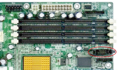
I am not even able to find bios or pinout schemes for front panel….
Probably might help if you detail exactly what you're trying to achieve with processors & busses on any of these boards.
The PowerEdge 1500SC uses the ServerWorks HE-SL chipset which differs from the LE (and its block diagram I PMd you) by having not 2 but 3 PCI busses (32-bit 33MHz, 64-bit 33MHz & 64-bit 33 / 66MHz)
The docs are available online, but they probably don't show the pinouts you're looking for. You can get BIOS, docs & support files here
Will look into it. But without the pinout scheme would be difficult to fire up the board…
All I am trying to do is to play with PCI to PCIexpress adapters with VGA.
DELL don't seem to publish the pinout anywhere themselves, but it's not difficult to make an educated guess based on online searches...
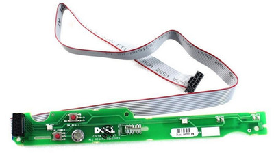
...the actual front panel only serves 4 functions - power on, reset, power LED and activity / storage LED, all of which are built into a small PCB and cable attached to the server case
The circuit traces on the front panel PCB give clues about where the likeliest pinouts for each function are but as there are so few likely combinations, it wouldn't take long to safely test & confirm for each.
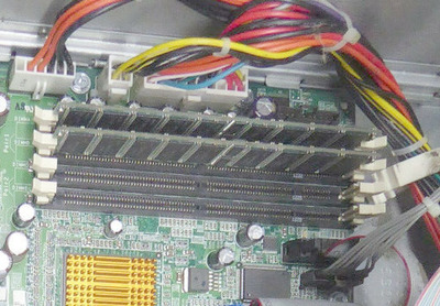
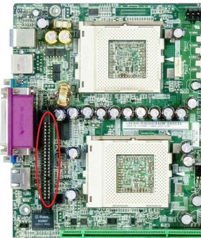
Also, if you haven't already noticed, another thing to mention about this board is that the installation of a second processor requires the addition a voltage regulator module (VRM) in the dedicated slot. There seems to be two different part numbers for this, depending on whether you're using a redundant power supply or not - 0M495 for redundant PSUs or else 7G041 for any others (obviously worth double-checking).
I already noticed that piece of PCB, but I don’t think the seller included it, so I do not have a clue on how to guess anything.
The VRM module is another story, maybe I will search for it, maybe not, it is not crucial for my experiments at the moment.