First post, by Susanin79
Greetings,
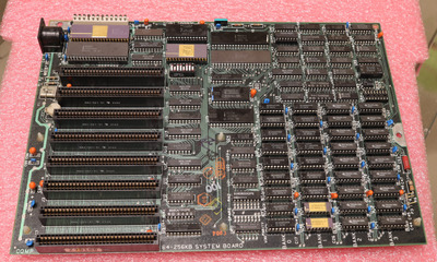
Recently I bought a nice IBM PC XT 5160 in a quite good condition for it's age. One of the issues I faced with this PC is that it constantly boot with the BIOS post video adapter error - 1 long beep then 2 short beeps.
I tried several video adapters that I have (5 different EGA and 3 VGA, unfortunately CGA card that came with this PC does not work yet, and I has no MDA card to test), with the corresponding dip switch settings for this types of adapters. I was able to get a clean picture, but the system continue to boot with this beeps.
Performing some tests on this machine I decided to check the dip switch block as it described in this article. Based on the results of the BASIC program, described in test one I got:
run 0, all switches are off: (0 0 0 0 0 0 0 0) result = 255
run 1, first switch is on: (1 0 0 0 0 0 0 0) result = 254
run 2, second switch is on: (0 1 0 0 0 0 0 0) result = 253
run 3, third switch is on: (0 0 1 0 0 0 0 0) result = 251
run 4, fourth switch is on: (0 0 0 1 0 0 0 0) result = 247
run 5, fifth switch is on: (0 0 0 0 1 0 0 0) result = 239
run 6, sixth switch is on: (0 0 0 0 0 1 0 0) result = 255
run 7, seventh switch is on: (0 0 0 0 0 0 1 0) result = 191
run 8, eighth switch is on: (0 0 0 0 0 0 0 1) result = 127
So the switch 6 constantly is in off position. Is there any way to fix this error other than replace the whole DIP switches module? The motherboard that came with this PC is one of the earliest that was produced for 5160 models and I'd like to keep it in original condition and build an authentic PC. Did it will work if I solder a small wire between corresponding DIP switch legs on the back of the plate?
One more question. Is it really rare and it is one of the earlier revisions of motherboard for 5160? Based of this article, there is only few owners of this board with the installed ROM's '5000026' and '5000027', so if it is true, then I'd like to keep it as it is.