VOGONS


Adding 3.3v to pci adapter(Released)

Topic actions

Reply 160 of 192, by NachtRave

User metadata
Rank Member
Rank
Member
CalamityLime wrote on 2022-12-27, 12:20:

Hey. Nice little board and some good points

However those traces look a little thin for 10 watts. According to a trace thickness calculator that i use as some bit of measure, they should be around 1.4mm thick for default 1oz copper of prototype boards.

Thanks for the feedback! You're absolutely right, and I thank you for reminding me of doing that.

How about 35mils? Is that big enough? Updated post. 20C for 3A on a trace calculator. Should be fine.

Reply 161 of 192, by Sphere478

User metadata
Rank l33t++
Rank
l33t++
NachtRave wrote on 2022-12-27, 23:28:
CalamityLime wrote on 2022-12-27, 12:20:

Hey. Nice little board and some good points

However those traces look a little thin for 10 watts. According to a trace thickness calculator that i use as some bit of measure, they should be around 1.4mm thick for default 1oz copper of prototype boards.

Thanks for the feedback! You're absolutely right, and I thank you for reminding me of doing that.

How about 35mils? Is that big enough? Updated post. 20C for 3A on a trace calculator. Should be fine.

Make them as big as will fit. Or even better use floods and zones 😀

Edit: yeah, you should be able to use floods to route the power on that. Then just a few traces for the resistors.

Sphere's PCB projects.
-
Sphere’s socket 5/7 cpu collection.
-
SUCCESSFUL K6-2+ to K6-3+ Full Cache Enable Mod
-
Tyan S1564S to S1564D single to dual processor conversion (also s1563 and s1562)

Reply 162 of 192, by Sphere478

User metadata
Rank l33t++
Rank
l33t++

btw, IDK if I mentioned this, but do not daisy chain these. the taps are on both sides so that you can use whichever is closer but you should run separate wires from source for each unit. or use an external bus like copper tape down the side of the slots.

you can see what I mean here.
The coolest socket 7 motherboard that you’ve never heard of
file.php?id=152688&mode=view

Last edited by Sphere478 on 2022-12-28, 20:15. Edited 1 time in total.

Sphere's PCB projects.
-
Sphere’s socket 5/7 cpu collection.
-
SUCCESSFUL K6-2+ to K6-3+ Full Cache Enable Mod
-
Tyan S1564S to S1564D single to dual processor conversion (also s1563 and s1562)

Reply 163 of 192, by CalamityLime

User metadata
Rank Member
Rank
Member
NachtRave wrote on 2022-12-27, 23:28:
CalamityLime wrote on 2022-12-27, 12:20:

Hey. Nice little board and some good points

However those traces look a little thin for 10 watts. According to a trace thickness calculator that i use as some bit of measure, they should be around 1.4mm thick for default 1oz copper of prototype boards.

Thanks for the feedback! You're absolutely right, and I thank you for reminding me of doing that.

How about 35mils? Is that big enough? Updated post. 20C for 3A on a trace calculator. Should be fine.

should be fine.

Be Happy, it's only going to get worse.
- Projects
Limes Strange 3D models
USB-2-232

Reply 164 of 192, by Sphere478

User metadata
Rank l33t++
Rank
l33t++

Got the latest version in for my freeway mobo (this is based on the latest version in this thread)

Attachments

Sphere's PCB projects.
-
Sphere’s socket 5/7 cpu collection.
-
SUCCESSFUL K6-2+ to K6-3+ Full Cache Enable Mod
-
Tyan S1564S to S1564D single to dual processor conversion (also s1563 and s1562)

Reply 165 of 192, by NachtRave

User metadata
Rank Member
Rank
Member

Got the PCBs in today but still waiting on the mosfet and caps and such. Excited to get this into the slot to try out.

I'm taking it you just basically solder where there are exposed vias (essentially)? Nothing too fancy really?

Attachments

  • FmXXazTaEAEeE2D.jpg
    Filename
    FmXXazTaEAEeE2D.jpg
    File size
    378.05 KiB
    Views
    1128 views
    File license
    Public domain

Reply 166 of 192, by NachtRave

User metadata
Rank Member
Rank
Member

Alright, so first thing I noticed right off the bat here is that on the back of these PCI ports here on this ASUS TXP4 board, 3 of the ports have these large ground pads at the head of the port (except for last one). Those are going to cause issues cause on the motherboard side of the PCB with the 3v3 pad exposed. That’s gonna cause a ground short right away.

I didn’t really want to mount it on this specific lower PCI port (since it blocks usage of one of the ISA ports), so I may just cover the ground plane up with some kapton tape.

Otherwise it’s a perfect fit! :3

Attachments

Last edited by NachtRave on 2023-01-13, 20:12. Edited 1 time in total.

Reply 167 of 192, by Sphere478

User metadata
Rank l33t++
Rank
l33t++

Yep kapton tape is the way to solve that.
😀

Looking good! Be sure to check for shorts before powering on.

Sphere's PCB projects.
-
Sphere’s socket 5/7 cpu collection.
-
SUCCESSFUL K6-2+ to K6-3+ Full Cache Enable Mod
-
Tyan S1564S to S1564D single to dual processor conversion (also s1563 and s1562)

Reply 168 of 192, by NachtRave

User metadata
Rank Member
Rank
Member

All connections with meter passing. Left 3.3VSB pin to NC (same as mmx_91 above was saying), since it too isn’t connected to anything on this Asus TXP4 board either, and I can always come back and close it to 3v3.

Still have to wait for caps/fet for the PSU circuit there, but I am hopeful that will be all that is needed. Am going to have my scope hooked up to it on power up to make sure I see a steady supply.

Attachments

Reply 169 of 192, by Sphere478

User metadata
Rank l33t++
Rank
l33t++

Since you have a scope, you could do some tests with different decoupling capacitors if you can. Let us know what values you think are best for this.

Sphere's PCB projects.
-
Sphere’s socket 5/7 cpu collection.
-
SUCCESSFUL K6-2+ to K6-3+ Full Cache Enable Mod
-
Tyan S1564S to S1564D single to dual processor conversion (also s1563 and s1562)

Reply 170 of 192, by NachtRave

User metadata
Rank Member
Rank
Member
Sphere478 wrote on 2023-01-13, 20:35:

Since you have a scope, you could do some tests with different decoupling capacitors if you can. Let us know what values you think are best for this.

Haha, you are dramatically over-estimating my skill level with electronics. :3 I just am good at the soldering part, I'm still very much a student in the world of circuit analysis and design. I get the gist of it all, I have an idea of several simple circuits that are popular, but I am not sure where to begin there. I guess I could get a cap kit with a bunch of different little capacitors and then go from there? Hmm, well, we'll see what I can figure out. I might make some more mods to the above PSU board until I get it to where it needs to be, but I'll keep in touch. Hopefully going to get some components soon here.

Reply 171 of 192, by Sphere478

User metadata
Rank l33t++
Rank
l33t++
NachtRave wrote on 2023-01-14, 01:39:
Sphere478 wrote on 2023-01-13, 20:35:

Since you have a scope, you could do some tests with different decoupling capacitors if you can. Let us know what values you think are best for this.

Haha, you are dramatically over-estimating my skill level with electronics. :3 I just am good at the soldering part, I'm still very much a student in the world of circuit analysis and design. I get the gist of it all, I have an idea of several simple circuits that are popular, but I am not sure where to begin there. I guess I could get a cap kit with a bunch of different little capacitors and then go from there? Hmm, well, we'll see what I can figure out. I might make some more mods to the above PSU board until I get it to where it needs to be, but I'll keep in touch. Hopefully going to get some components soon here.

Yeah, You just put your scope on the power pins or on some traces on like a video card or something and just play around with the capacitors until you get the smoothest line
I suspect that you will be using pretty small value capacitors but basically different frequencies respond to different capacitor sizes

And then you would try like a different card to see if the values for it were different I suspect it’s entirely possible that we would just have to select a capacitor to tell everyone to get them to do the most good over the variety of cards but it’s kind of difficult To decide what that might be because certainly each card would have probably a different value capacitor that would be ideal

Sphere's PCB projects.
-
Sphere’s socket 5/7 cpu collection.
-
SUCCESSFUL K6-2+ to K6-3+ Full Cache Enable Mod
-
Tyan S1564S to S1564D single to dual processor conversion (also s1563 and s1562)

Reply 172 of 192, by NachtRave

User metadata
Rank Member
Rank
Member
Sphere478 wrote on 2023-01-14, 02:07:
Yeah, You just put your scope on the power pins or on some traces on like a video card or something and just play around with th […]
Show full quote
NachtRave wrote on 2023-01-14, 01:39:
Sphere478 wrote on 2023-01-13, 20:35:

Since you have a scope, you could do some tests with different decoupling capacitors if you can. Let us know what values you think are best for this.

Haha, you are dramatically over-estimating my skill level with electronics. :3 I just am good at the soldering part, I'm still very much a student in the world of circuit analysis and design. I get the gist of it all, I have an idea of several simple circuits that are popular, but I am not sure where to begin there. I guess I could get a cap kit with a bunch of different little capacitors and then go from there? Hmm, well, we'll see what I can figure out. I might make some more mods to the above PSU board until I get it to where it needs to be, but I'll keep in touch. Hopefully going to get some components soon here.

Yeah, You just put your scope on the power pins or on some traces on like a video card or something and just play around with the capacitors until you get the smoothest line
I suspect that you will be using pretty small value capacitors but basically different frequencies respond to different capacitor sizes

And then you would try like a different card to see if the values for it were different I suspect it’s entirely possible that we would just have to select a capacitor to tell everyone to get them to do the most good over the variety of cards but it’s kind of difficult To decide what that might be because certainly each card would have probably a different value capacitor that would be ideal

Well I guess I'll be looking for a capacitor sizing kit next then. I'm a learning computa! I'm learning! 😄

Reply 173 of 192, by Sphere478

User metadata
Rank l33t++
Rank
l33t++

Everyone so far has not been using capacitors fyi. This is a added feature now. 😀 So you of course can choose to wait until someone else does this or not do it and leave well enough alone also. 😀

Sphere's PCB projects.
-
Sphere’s socket 5/7 cpu collection.
-
SUCCESSFUL K6-2+ to K6-3+ Full Cache Enable Mod
-
Tyan S1564S to S1564D single to dual processor conversion (also s1563 and s1562)

Reply 174 of 192, by NachtRave

User metadata
Rank Member
Rank
Member

Pffffpffpffpffffpffpfffffff leave it alone, lololol, you sure are funny. :3

I am sure that we'll get something half decent, if not fairly close. One of the things that I figured would be you'd need different sized caps to handle the various loads, and I think that the variance in caps that I am getting a hold of (directly pulling from the DX4 overdrive PSU circuit) is a fair number of them. I also have some other weird sized caps around my lab that I can test, even if they are for far larger voltages or capacities. Seems like a fairly straightforward operation then - basically counteracting the frequencies causing power losses with capacitors. Seems like a good newbie task for someone like me to tackle.

Are there any special settings for this Rigol DS1202 scope I have that might be useful when looking at the signal? I would assume you'd need some way to capture the signal and then zoom in, and I guess I kind of understand the basics of the scope but not exactly how to stop and replay a recording, for instance. Any tips that you can think of? I could also probably RTFM but that would involve me having to find my glasses and spend an entire morning on it.

Edit: Update: I broke one of my test leads. =( It's okay, there were two of them in there, but the "manual" was mostly in Chinese and only really a little fold-out. I guess there's an online manual then? Or they just assume you aren't someone biting off more than they could chew like me? Anyways, I'm off to a great start! 😄

Reply 175 of 192, by Sphere478

User metadata
Rank l33t++
Rank
l33t++

Not sure how to set up your scope. Just start with the signal and see what frequencies are there. Try to solve them with the capacitors.

Sphere's PCB projects.
-
Sphere’s socket 5/7 cpu collection.
-
SUCCESSFUL K6-2+ to K6-3+ Full Cache Enable Mod
-
Tyan S1564S to S1564D single to dual processor conversion (also s1563 and s1562)

Reply 176 of 192, by NachtRave

User metadata
Rank Member
Rank
Member

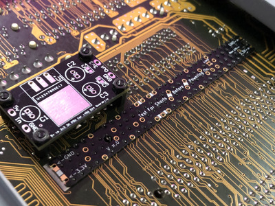
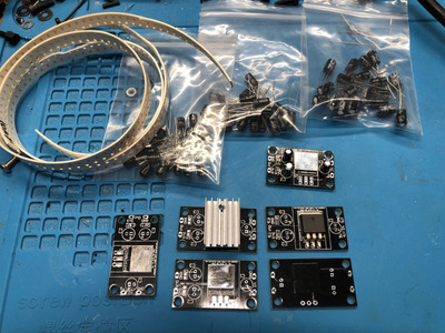
Alright! I apologize for the delay - had to get the new boards from PCBWay and did the cheapo shipping. Anyways, I believe I have it all together. I have double checked all my connections and everything seems fine.

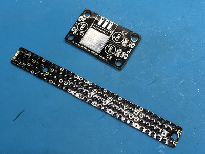
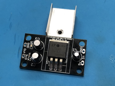
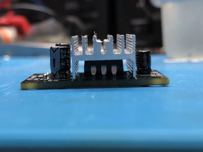
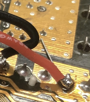
One feedback item I would give is that the cap slot there on the side of the PCB is pretty tiny for an 0603 sized cap. I would recommend anyone to go up a size or two, it’s otherwise just a really hard little bugger to get in there and keep situated. I did get mine in there, but took a pad with it. It’s all fine in the end but a bigger component would had made that easier.

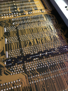
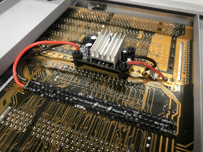
Otherwise, wow. The plate on the back there fits like a glove and I am thrilled to be at this spot. However, will this be enough? Will the i486 DX4 Overdrive PSU circuit work with this cheapo un-branded 45$ Nvidia 5500? Will it accept 5v signaling? Time will tell if we see any black smoke.

I’m kind of afraid to turn it on, despite checking all my connections. I might table this for a bit, to do some research on the 5500 Nvidia chipset to see if it’s 5v tolerant. I’m hopeful, but maybe I don’t want to fry my retro PC just yet. :3

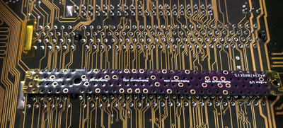
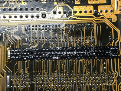
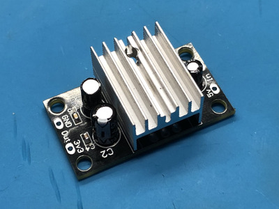
The PCB I made there tho seems to be perfect tho! Definitely the right move with all the feedback items ya’ll gave me, with widening the circuit pathways and getting room for a heat sync. The mounting angle is also very intentional, so that hot air rises and bring in colder air underneath it.

I’ll let ya’ll know how it turns out though. Gonna go back to coding for now.

Attachments

Reply 177 of 192, by Sphere478

User metadata
Rank l33t++
Rank
l33t++

What is with the wire laying on the mobo where you tap for the psu?

Attachments

Sphere's PCB projects.
-
Sphere’s socket 5/7 cpu collection.
-
SUCCESSFUL K6-2+ to K6-3+ Full Cache Enable Mod
-
Tyan S1564S to S1564D single to dual processor conversion (also s1563 and s1562)

Reply 179 of 192, by NachtRave

User metadata
Rank Member
Rank
Member
Sphere478 wrote on 2023-02-18, 22:09:

What is with the wire laying on the mobo where you tap for the psu?

🤣. That was just a random piece of solder wire that had fallen there. I just didn't catch it in time for the photo, haha. :3

Well, I worked up the courage to test it... And, I got a post beep! I immediately turned it back off, cause, me'sa scared. :3

I guess that means that I just now need to hook up a monitor to it and test but hearing that post beep and not seeing any magic black smoke pop off as soon as it was turned on is an amazing sign.

I mean, without the mods, it wouldn't even post beep. It would do a vid-card-not-detected beep code, so I am definitely thinking this may actually work. I just need to hook it all back up now and make it nice. I also had an AWE64 Gold audio card that I wanted to put alongside this orpheus.