VOGONS


First post, by Sphere478

User metadata
Rank l33t++
Rank
l33t++

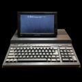
I’ve had this Idea floating around in my head for a little while of making a acrylic retro laptop out of a AT mobo, some pci cables/right angle adapters and a pico psu and lcd screen.

Anyway, aside from all that which I will probably never get around to doing. Are there pico AT psus?

I know there are ATX ones and adapter cables. But wouldn’t it be cool to have one that plugged into the at slot?

Last edited by Sphere478 on 2022-12-20, 22:54. Edited 7 times in total.

Sphere's PCB projects.
-
Sphere’s socket 5/7 cpu collection.
-
SUCCESSFUL K6-2+ to K6-3+ Full Cache Enable Mod
-
Tyan S1564S to S1564D single to dual processor conversion (also s1563 and s1562)

Reply 2 of 156, by Sphere478

User metadata
Rank l33t++
Rank
l33t++
Doornkaat wrote on 2022-02-20, 07:28:

I don't know of any but you could probably draw up an adaptor PCB pretty quickly in KiCad.
Probably the neatest alternative to using an adaptor cable.

Not among my skill sets, but that had occurred to me. 🤔 it would probably be a pretty easy circuit to assemble, and design. Could probably just copy a pico atx mostly and make a few select changes.

Sphere's PCB projects.
-
Sphere’s socket 5/7 cpu collection.
-
SUCCESSFUL K6-2+ to K6-3+ Full Cache Enable Mod
-
Tyan S1564S to S1564D single to dual processor conversion (also s1563 and s1562)

Reply 3 of 156, by Doornkaat

User metadata
Rank l33t
Rank
l33t

I was thinking more of a passive PCB with an ATX connector for the pico PSU, AT connector for the mainboard (don't know if anything is avaliable to mount on PCBs, so maybe something would have to be imrovised with a crimp connector, short cables and superglue) and a header to connect the switch that is used to start the ATX PSU.

Reply 4 of 156, by Doornkaat

User metadata
Rank l33t
Rank
l33t

I learned KiCad basics with YouTube videos to make that GFD clone. That adaptor PCB is no more complicated to design and an ideal beginners' project. I can only encourage you to try and make one because it is very satisfying to get that PCB in the mail, assemble it and see your own design in action. Even if it's just something small and entirely passive like that adaptor.

Edit: You could even include mounting and air holes for a 60mm fan to actively cool the pico PSU.
Edit2: And you can include -5V generation from the -12V rail.

Reply 5 of 156, by wiretap

User metadata
Rank Oldbie
Rank
Oldbie

A simple adapter like this should work, and it provides -5V too. Just plug into the AT motherboard, and plug the PicoPSU in on top.

front-3d.png
Filename
front-3d.png
File size
61.65 KiB
Views
3926 views
File license
CC-BY-4.0
back-3d.png
Filename
back-3d.png
File size
73.11 KiB
Views
3926 views
File license
CC-BY-4.0

My Github
Circuit Board Repair Manuals

Reply 6 of 156, by Doornkaat

User metadata
Rank l33t
Rank
l33t
wiretap wrote on 2022-02-20, 19:39:

A simple adapter like this should work, and it provides -5V too. Just plug into the AT motherboard, and plug the PicoPSU in on top.

front-3d.png

back-3d.png

Exactly that, nice!
Does it have a header for the soft power switch though?

Reply 7 of 156, by wiretap

User metadata
Rank Oldbie
Rank
Oldbie
Doornkaat wrote on 2022-02-20, 19:44:
wiretap wrote on 2022-02-20, 19:39:

A simple adapter like this should work, and it provides -5V too. Just plug into the AT motherboard, and plug the PicoPSU in on top.

front-3d.png

back-3d.png

Exactly that, nice!
Does it have a header for the soft power switch though?

Since it is AT, I have PS-ON and GND trace connected, and you'd just run the Pico-PSU power connector through the case's AT power switch. But a jumper header could easily be added for low voltage / low current latching switches.

edit: here..

front-3d.png
Filename
front-3d.png
File size
55.66 KiB
Views
3895 views
File license
CC-BY-4.0
back-3d.png
Filename
back-3d.png
File size
75.04 KiB
Views
3895 views
File license
CC-BY-4.0

My Github
Circuit Board Repair Manuals

Reply 8 of 156, by Doornkaat

User metadata
Rank l33t
Rank
l33t
wiretap wrote on 2022-02-20, 20:01:
Doornkaat wrote on 2022-02-20, 19:44:
wiretap wrote on 2022-02-20, 19:39:

A simple adapter like this should work, and it provides -5V too. Just plug into the AT motherboard, and plug the PicoPSU in on top.

front-3d.png

back-3d.png

Exactly that, nice!
Does it have a header for the soft power switch though?

Since it is AT, I have PS-ON and GND trace connected, and you'd just run the Pico-PSU power connector through the case's AT power switch. But a jumper header could easily be added for low voltage / low current latching switches.

I thought this way it would be more convenient to install and more compatible when using a case that only allows for those typical small ATX case switches to be installed.
But on a real ATX switch disconnecting DC power is probably the more efficient alternative.👍

Reply 9 of 156, by wiretap

User metadata
Rank Oldbie
Rank
Oldbie

A regular ATX case switch wouldn't work since they are momentary. The power supply would turn on and back off the second you release the power button. The momentary switch works with an ATX motherboard since the motherboard logic holds the PS-ON signal to ground unless it gets a shutdown signal (high).

My Github
Circuit Board Repair Manuals

Reply 10 of 156, by Doornkaat

User metadata
Rank l33t
Rank
l33t
wiretap wrote on 2022-02-20, 20:31:

A regular ATX case switch wouldn't work since they are momentary. The power supply would turn on and back off the second you release the power button. The momentary switch works with an ATX motherboard since the motherboard logic holds the PS-ON signal to ground unless it gets a shutdown signal (high).

Yeah, I know. But a regular switch is avaliable in the same typical format. I have no idea wether they can handle the current a later AT system will demand to be supplied to the pico PSU. An AT switch obviously will be able to but you will have a hard time installing an AT switch in many ATX cases. With a header for a (regular) switch (to replace the momentary switch in ATX cases) you can always just put a jumper over the header and still install a switch on the DC supply going to the pico PSU.

I'm not trying to take a dump on your design, just in case it appears I was attempting to do so! It's just have a different approach.

Reply 11 of 156, by snufkin

User metadata
Rank Oldbie
Rank
Oldbie

It'd be three(?) extra components, but could maybe fudge it with a suitably debounced flip-flop running off +5SB, to make an ATX case switch act as a toggle on/off? It might need to switch via a FET to short PSON to GND, or might work directly off of the flip-flip output. I don't know what the current requirements would be actively driving PSON to +5SB or GND, compared to shorting to ground or leaving open.

[edit: incidentally, I knew something was bugging me about the power pinout for the IBM Model 25 I've been looking up, and I've just realised it's that it has a more-or-less AT pinout, except that pin 2 is Ground on the Model 25 and not +5V. That sounds like an unfortunate difference.]

Last edited by snufkin on 2022-02-20, 21:01. Edited 1 time in total.

Reply 12 of 156, by wiretap

User metadata
Rank Oldbie
Rank
Oldbie
Doornkaat wrote on 2022-02-20, 20:43:
wiretap wrote on 2022-02-20, 20:31:

A regular ATX case switch wouldn't work since they are momentary. The power supply would turn on and back off the second you release the power button. The momentary switch works with an ATX motherboard since the motherboard logic holds the PS-ON signal to ground unless it gets a shutdown signal (high).

Yeah, I know. But a regular switch is avaliable in the same typical format. I have no idea wether they can handle the current a later AT system will demand to be supplied to the pico PSU. An AT switch obviously will be able to but you will have a hard time installing an AT switch in many ATX cases. With a header for a (regular) switch (to replace the momentary switch in ATX cases) you can always just put a jumper over the header and still install a switch on the DC supply going to the pico PSU.

I'm not trying to take a dump on your design, just in case it appears I was attempting to do so! It's just have a different approach.

You're good. I'll take any feedback. 😀

I just originally thought about it from a design perspective and what type of equipment it would power, and what type cases that hardware normally goes into. Since it is powering an AT board, that usually means AT mounting. If you're putting an AT board in an ATX case, that already means you're going to be modding it with drilling and tapping new standoff locations at a minimum, maybe making a new backplate for the case if it isn't full ATX (unless you nix some slots). I figured snipping the PicoPSU power cable and putting the AT power switch in series would be typical. However, I do see the need for the jumper in case other people wanted to replace an ATX switch with a latching switch and just run it to the jumper on the PICO-AT board. I've now incorporated that into the design, so thanks for bringing it up.

My Github
Circuit Board Repair Manuals

Reply 13 of 156, by wiretap

User metadata
Rank Oldbie
Rank
Oldbie
snufkin wrote on 2022-02-20, 20:53:

It'd be three(?) extra components, but could maybe fudge it with a suitably debounced flip-flop running off +5SB, to make an ATX case switch act as a toggle on/off? It might need to switch via a FET to short PSON to GND, or might work directly off of the flip-flip output. I don't know what the current requirements would be actively driving PSON to +5SB or GND, compared to shorting to ground or leaving open.

That could be done. You'd need a debouce circuit for the switch, and flip flop. There's probably 4 or 5 different ways to do it easily, but of course it just adds to the cost. It would probably be better just to make a postage stamp size PCB separate from the PSU interposer board if you really needed to use a momentary switch.

My Github
Circuit Board Repair Manuals

Reply 14 of 156, by Doornkaat

User metadata
Rank l33t
Rank
l33t
wiretap wrote on 2022-02-20, 20:55:

You're good. I'll take any feedback. 😀

I just originally thought about it from a design perspective and what type of equipment it would power, and what type cases that hardware normally goes into. Since it is powering an AT board, that usually means AT mounting. If you're putting an AT board in an ATX case, that already means you're going to be modding it with drilling and tapping new standoff locations at a minimum, maybe making a new backplate for the case if it isn't full ATX (unless you nix some slots). I figured snipping the PicoPSU power cable and putting the AT power switch in series would be typical. However, I do see the need for the jumper in case other people wanted to replace an ATX switch with a latching switch and just run it to the jumper on the PICO-AT board. I've now incorporated that into the design, so thanks for bringing it up.

😃👍
I really appreciate all the things you provide to the community, especially this kind of ease-of-use solution.

Edit: I just realised that with the switch header this will also serve as a very tidy ATX->AT adaptor that reduces cable clutter compared to the usual adaptor cables (and provides -5V obviously)!

Reply 15 of 156, by wiretap

User metadata
Rank Oldbie
Rank
Oldbie

True, I thought about that when making it, 🤣. It could be a little more compact, but I stuck the L7905 between the two connectors. It could also go behind the ATX connector if the leads were clipped short.

Anyway, here's the project files attached. (rev0.2)
Mouser BOM link: https://www.mouser.com/ProjectManager/Project … ssID=e02f763ac2

Note.. I haven't built or tested this yet, so please verify the design if you plan on using it. KiCAD 5 was used. It is a 4 layer board.. the inner two layers are just massive 12V and 5V planes, so there should be no issue with drawing too much current on those, 🤣. I mean, I wouldn't go past what a PicoPSU can provide..

Board cost is $8 for 5 when you upload it to JLCPCB. Mouser cart is about $11. So, pretty cheap to build.

[attachment=-1]bom.PNG[/attachment]

front-3d.png
Filename
front-3d.png
File size
47.16 KiB
Views
3773 views
File license
CC-BY-4.0
back-3d.png
Filename
back-3d.png
File size
81.08 KiB
Views
3773 views
File license
CC-BY-4.0

Attachments

Last edited by wiretap on 2022-02-20, 22:41. Edited 2 times in total.

My Github
Circuit Board Repair Manuals

Reply 16 of 156, by Sphere478

User metadata
Rank l33t++
Rank
l33t++
wiretap wrote on 2022-02-20, 20:01:
Since it is AT, I have PS-ON and GND trace connected, and you'd just run the Pico-PSU power connector through the case's AT powe […]
Show full quote
Doornkaat wrote on 2022-02-20, 19:44:
wiretap wrote on 2022-02-20, 19:39:

A simple adapter like this should work, and it provides -5V too. Just plug into the AT motherboard, and plug the PicoPSU in on top.

front-3d.png

back-3d.png

Exactly that, nice!
Does it have a header for the soft power switch though?

Since it is AT, I have PS-ON and GND trace connected, and you'd just run the Pico-PSU power connector through the case's AT power switch. But a jumper header could easily be added for low voltage / low current latching switches.

edit: here..

front-3d.png

back-3d.png

I’ve heard of people exchanging the case switch with a on/off switch instead of a monentary.

That’s a cool idea, that adapter. I like how it’s mounted using that, instead of flopping all over the place.

Yeah, only thing I can think of to improve the design is making it shorter by putting the fet off to the side or something, but then you run into issues with it hitting things on some mobos. Maybe two smaller smd style on opposite sides in parallel

Sphere's PCB projects.
-
Sphere’s socket 5/7 cpu collection.
-
SUCCESSFUL K6-2+ to K6-3+ Full Cache Enable Mod
-
Tyan S1564S to S1564D single to dual processor conversion (also s1563 and s1562)

Reply 17 of 156, by wiretap

User metadata
Rank Oldbie
Rank
Oldbie

Just noticed one improvement that could be made with this design.. at the P8/P9 connector, the PCB is wider than it needs to be. This can cause clearance issues with some motherboards that may have something right next to the power connector. I'll issue a rev0.2 with that fixed. edit: updated the files in the post above

My Github
Circuit Board Repair Manuals

Reply 19 of 156, by Sphere478

User metadata
Rank l33t++
Rank
l33t++

Idea.

Move fet up on back higher than the atx plug. And make them small smd in parallel

Will be as short and small as possible now

Attachments

Sphere's PCB projects.
-
Sphere’s socket 5/7 cpu collection.
-
SUCCESSFUL K6-2+ to K6-3+ Full Cache Enable Mod
-
Tyan S1564S to S1564D single to dual processor conversion (also s1563 and s1562)