Reply 80 of 221, by Sphere478

Rank
l33t++
- Rank
- l33t++
Beta 3.141
okay. I'm liking this one. Might prototype it.
Beta 3.141
okay. I'm liking this one. Might prototype it.
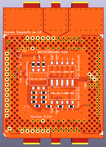
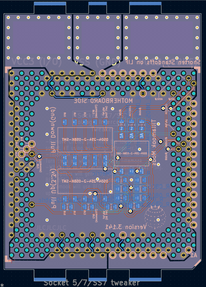
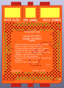
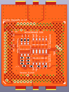
3.1415
Widened it.
I was having trouble routing the vccc3 and vcc2 the way I liked and meeting amperage goals. Ultimately I decided to add more room on the sides, this solved it. It's basically exactly the same size as the socket now.
It looks like 0.8mm or 1mm PCB thicknesses will work best for this. I'm betting on 0.8mm being the best.
Gonna put in a order now.
It looks great. Very clean.
Hey
Based off of my tinkering with making a new vrm for my own socket 7 board, Sphere asked me to look into making a step down voltage converter for the tweeker.
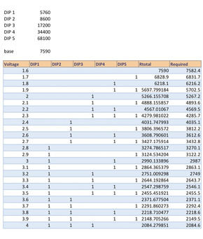
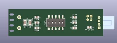
For voltages I have 1.6 -> 4.0 available in increments of 0.1v from 6 different resistors. Attached is a PDF of an excel sheet I used to confirm I had my values correct. The website doesn't let me attach excel sheets, I assume because they store your name somewhere in the sheet.
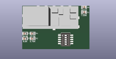
The image is of the parts I have in the circuit currently. I'll likely swap out the smaller dip switch for a larger one and some filter caps, that's minor things.
Be Happy, it's only going to get worse.
- Projects
Limes Strange 3D models
USB-2-232
Thanks Kahenraz
Here ya go Calamitylime. 😀
CalamityLime wrote on 2022-06-23, 14:56:Hey […]
Hey
Based off of my tinkering with making a new vrm for my own socket 7 board, Sphere asked me to look into making a step down voltage converter for the tweeker.
For voltages I have 1.6 -> 4.0 available in increments of 0.1v from 6 different resistors. Attached is a PDF of an excel sheet I used to confirm I had my values correct. The website doesn't let me attach excel sheets, I assume because they store your name somewhere in the sheet.
The image is of the parts I have in the circuit currently. I'll likely swap out the smaller dip switch for a larger one and some filter caps, that's minor things.
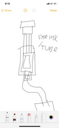
This is kinda what we were thinking (Pic below). Have it plug into a molex. And thermals allowing, we could insulate it for electrical reasons with shrink tube. Or a 3d printed housing.
Feel free to drop suggestions.
Of course the design allows user to choose the power source the hope is to make it as simple and easy to assemble as possible.
To that end Lime’s device uses a pre packaged VRM module available cheap. And only needs to use a mounting board to attach resistors, power lines and switches.
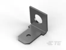
Btw, this is what I was thinking of using for a connection.
Solder it straight to the pad. It should work, be easy to find. Though I’ve been looking for maybe a better alternative. If anyone has a suggestion. Obviously you could solder the wire to the pad it’s self.
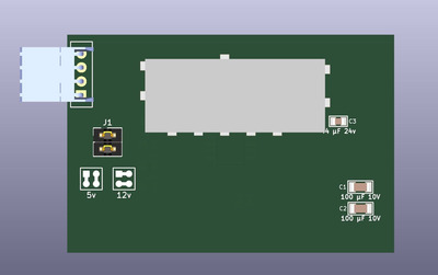
I was tinkering with the power in side of things.
Here is my thoughts so far on that:
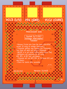
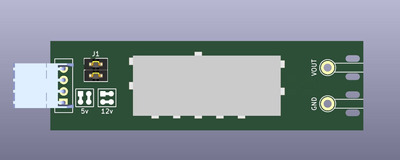
A floppy drive power connector (that I learned are called berg connectors) for power in and a set of jumpers to decide if the device should use the 5v rail or 12v rail. Using the 12v rail should be more efficient for the dc/dc unit and it could help stabilise an ATX supply that's being used in a 5v heavy system, however you could be using a PSU with a strong 5v rail that you may want to use.
I think the setting for the 5v or 12v is clear from the silk screen guide I added.
Be Happy, it's only going to get worse.
- Projects
Limes Strange 3D models
USB-2-232
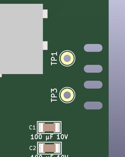
For power out I was going to make a hole you solder a wire to plus little spots for small zip ties to hold the wire to the PCB so the solder joint isn't taking that strain.
Be Happy, it's only going to get worse.
- Projects
Limes Strange 3D models
USB-2-232
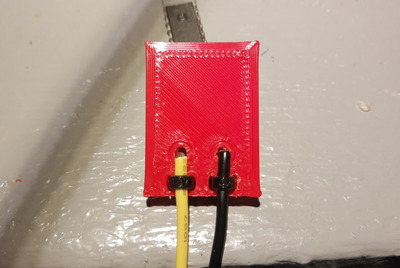
Like I said, for power out I was thinking solder pads for wires and holes for zip ties.
It would look a little something like this.
The little spade connectors might be easier to setup but I haven't used them enough myself to really comment on them.
Be Happy, it's only going to get worse.
- Projects
Limes Strange 3D models
USB-2-232
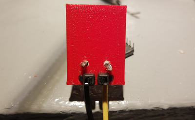
I dolled it up a small bit and I've decided that I'm going to 3d print it to see how well it actually works.
Obviously I can't solder to a 3d print but it'll give me a good clue if the idea if worth doing or not.
EDIT: attached an stl of my reference model that I prepared.
Be Happy, it's only going to get worse.
- Projects
Limes Strange 3D models
USB-2-232
berg connectors is very weak electrical connections ditto to molex. I prefer quality connectors that is designed for reliable power connections. The 4 or 6 pin mini ATX style connectors would be preferred, and spliced into power supply to get rid of unreliable plug connections.
Cheers,
Great Northern aka Canada.
pentiumspeed wrote on 2022-06-24, 20:56:berg connectors is very weak electrical connections ditto to molex. I prefer quality connectors that is designed for reliable power connections. The 4 or 6 pin mini ATX style connectors would be preferred, and spliced into power supply to get rid of unreliable plug connections.
Cheers,
Weak in what way?
I know some berg connectors I've come across pull out a little too easy for my liking but mostly they've been just fine. Molex I've had the opposite problem of them always gripping to damn hard. So I'm curious.
Be Happy, it's only going to get worse.
- Projects
Limes Strange 3D models
USB-2-232
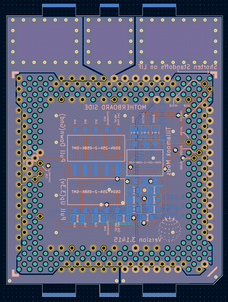
I've just been slowly laying out the PCB, getting it's footprints right and planning where to route traces.
So far this is what the board looks like and I included the kicad files in this post. What do ye think of this general direction? I know I can make the board smaller but I'm just showing the general shape here.
I'm still waiting on my printer to finish printing so I can print my little reference for the zip tie outputs.
Not a finalised release
Just to clarify, I don't consider this done yet and it is not to be considered working yet.
Be Happy, it's only going to get worse.
- Projects
Limes Strange 3D models
USB-2-232
Here we go, my little reference for the zip tie output is done. IT works decently well but it does come out with a good yank.
Be Happy, it's only going to get worse.
- Projects
Limes Strange 3D models
USB-2-232
Is there a spade connector design that can be attached with a screw and nut for strain relief that can then be soldered for solid electrical conductivity? I feel like just soldering it would be too weak and risk tearing off the pad after a few insertions and removals.
Maybe the one you linked can already do that; it has a hole in the center. I'm not sure how it would look or if it can be soldered to after a screw has been attached, since it will most likely be either zinc or some kind of steel that isn't a good surface for soldering to.
A space connector would be very clean though, and can be easily adapted to anything.
CalamityLime wrote on 2022-06-24, 18:59:Like I said, for power out I was thinking solder pads for wires and holes for zip ties.
It would look a little something like this.The little spade connectors might be easier to setup but I haven't used them enough myself to really comment on them.
This looks good actually.
Technically, we really only need one wire out btw. The ground connector is under the heatsink clip. So ignoring it is handy haha. The ground out and in should be common plane.
As for 5v vs 12v
It’s all being converted down from 120 or 230vac so it doesn’t really matter efficiency wise. But what does matter, is having more of that heat in the psu than in the converter.
The less the voltage drop across the pwm the less heat it will make.
We may actually even consider a sata power connector if this module supports 3.3v as a option for those using it for say 2.0v etc.
Though, the higher the voltage in, the less amps in so that helps. Not sure how many amps the 3.3v on a sata is rated to handle.
As far as wether or not a berg connector can take the load.
It can. Most interposers use that.
But in any case, I’m kinda thinking that we make the input accept wires and let the end user select their own male pigtail for the job whether that be berg, molex, or sata. Sata as a edge connector is also something to look into.
All in all we are only dealing with less than 30w here. The amperage only really gets significant on the converted side. So we can do whatever we want there, Unless talking about 3.3v input. We should look at the sata rating closely for that.
For reference:
3.3v in we are talking like 9a very little converter heat though
5v in we are talking 6a little more converter heat here
12v we are talking only 2.5a but the most converter heat.
Of course output: amps remain the same across all options. But vary by cpu.
Kahenraz wrote on 2022-06-25, 00:13:Is there a spade connector design that can be attached with a screw and nut for strain relief that can then be soldered for solid electrical conductivity? I feel like just soldering it would be too weak and risk tearing off the pad after a few insertions and removals.
Maybe the one you linked can already do that; it has a hole in the center. I'm not sure how it would look or if it can be soldered to after a screw has been attached, since it will most likely be either zinc or some kind of steel that isn't a good surface for soldering to.
A space connector would be very clean though, and can be easily adapted to anything.
The tweaker can be drilled in the middle of the pad without causing change in connections.
I considered a hole but that makes soldering a wire to it harder.
Also a screw or nut would probably protrude too far. So a rivet of some kind would probably be more ideal.
If it’s a consern, put the spade in the middle of the wire.
In any case, I think solder is probably adequate. And a thru hole fastener is probably only a good idea on paper, not in practice. I think even a loose connection on the spade is probably unlikely to cause it to desolder. And again, the solution is to put the spade in the middle of the wire.
As for shape size, etc.
I was thinking shrink tubing this would make a lot of sense if heat was manageable. And would help with electrical shorting issues to case/components. To that end, it should be as thin as possible, and tapered in at the ends. With a protruding part for configuration.
Otherwise the user will have to also source a 3d printer. And I’m. All about a reduced BOM and ease of assembly.
We should also consider that people may want to cable manage this and hide it in places. So size is important. And the user being able to use wires to make it longer or shorter is also handy.
TBH I think that sata power for 3.3v would be a mistake.
Personally I don't feel like sata power is as flexible as Molex or even the berg connector, might be too hard to solder since there are a lot more pins to them compared to most things. Plus it's not friendly to AT psu's
Tell me what you want the in and out to be , this is your thing really, if you want sata power just say. I'm just following my own intuition on my end.
BTW, I did forget that I didn't need a ground out, oops.
Be Happy, it's only going to get worse.
- Projects
Limes Strange 3D models
USB-2-232
I also think that a floppy-style berg connector would work well. They are cheap and ubiquitous. Berg to larger molex connectors, SATA power connectors, 5V, 12V, or both, are also easily sourced and would be great when putting together kits, without having to crimp your own connectors (such as with spades).
yeah I was thinking that molex to berg cables are really cheap, so cheap I'd bet that you may have one or two kicking around your house. So if you wanted to DIY things, you could cut up a berg cable and rock on with your own thing.
I added the jumpers for 5/12v for the reasons I pointed out in the original post.
I also made the power out side a solder joint because it looks like you're expected to solder the wires to the interposer (unless I'm reading things wrong)
Be Happy, it's only going to get worse.
- Projects
Limes Strange 3D models
USB-2-232
CalamityLime wrote on 2022-06-25, 01:39:yeah I was thinking that molex to berg cables are really cheap, so cheap I'd bet that you may have one or two kicking around your house. So if you wanted to DIY things, you could cut up a berg cable and rock on with your own thing.
I added the jumpers for 5/12v for the reasons I pointed out in the original post.I also made the power out side a solder joint because it looks like you're expected to solder the wires to the interposer (unless I'm reading things wrong)
I’m going to examine it in physical form and see what makes sense. But spade or direct solder seems to be the way it is headed.