Reply 20 of 40, by Sphere478

- Rank
- l33t++
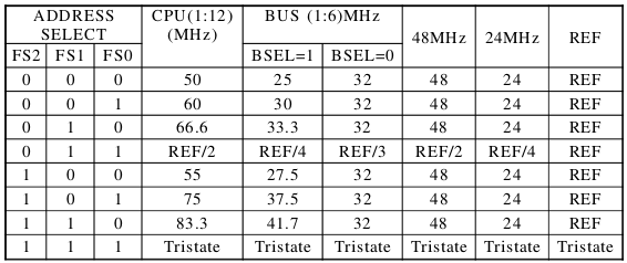
carlostex wrote on 2022-05-23, 05:04:I've been wondering if, one could use something like this to actually lower the final clock of a CPU. Like adding a 2 and 4 divider for the FSB just before the clock hits the CPU. The benefit of this would be to make a Socket 7 CPU much better suited for older games. For instance, setting the FSB on the board to 50Mhz and then setting a divider of 2 between them to lower the clock to 25Mhz. Then a 2x CPU multiplier would give a 50Mhz final CPU speed. This on a Pentium CPU + disabling Brancg prediction and v pipeline would properly give a good match for a 486DX2-66. Taking it further, a divider of 4 would lower the CPU to 25MHz. Lower CPU speeds opposed to just disabling the cache has a smoother slowdown in my experience. Would be nice to have this in a way that 486 speeds would be achievable without the disadvantages of disabling the cache.
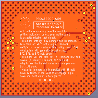
It might be possible to use a device like this to disable L2 cache. but the mobo usually has a setting for that.
however, I may have a clock related alternative for you.
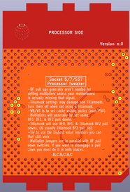
Many cyrix chips included a 1x multiplier setting that coincidentally, this tweaker can be used to set on older motherboards.
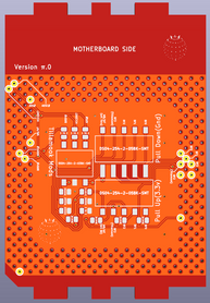
I'm going to upload a release version of this soon. stay tuned.
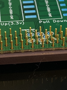
Unless anyone has thoughts otherwise, I think I'll leave the holes the same size and just basically make it standard that whomsoever wishes to use this is going to have to solder the pins. because the hole size does look pretty good.