VOGONS


Reply 20 of 66, by dekkit

User metadata
Rank Member
Rank
Member

Nice links!

A brief update, i still haven't pulled off the sound card to take a closer at the clock and data lines and also to take further measures and debug settings BUT i did try and insert a new cmos battery.

CMOS Battery
To keep cmos settings alive i wired in a cell battery of 3v (updated as it is not 3.3v ) which has done the job of keeping each hdd settings saved but i've noticed that on boot i'm getting weird timer errors. The clock seems to move forward - but i suspect when the power is off the 3v battery isn't tickling the crystal enough for accurate time keeping. Noting that the original dead battery was 3.5v - i was hoping that i could get away with a 3v - and it looks like it just works for the settings just not the clock.
Is that consistent with anyone else that has tried to replace a 3.5v with a 3v cell battery? if not a cell battery - is there a reliable place for 3.5v cmos batteries that fit into a holder that don't cost too much?

Note - I'll upload some more pictures over the coming weeks now that i've got some time off. I put the sbc in a perspex shell (mess and all), mounted the CF card holders, and wired the pico psu, and hacked apart an ipad lcd to make a sort of nice dos 486 mini setup as part of a test setup. Still a work in progress but its come a long way.

UPDATED corrected 3.3v to 3v

Last edited by dekkit on 2023-01-18, 22:34. Edited 2 times in total.

Reply 21 of 66, by weedeewee

User metadata
Rank l33t
Rank
l33t

could try a lir2032 button cell

Right to repair is fundamental. You own it, you're allowed to fix it.
How To Ask Questions The Smart Way
Do not ask Why !
https://www.vogonswiki.com/index.php/Serial_port

Reply 22 of 66, by dekkit

User metadata
Rank Member
Rank
Member
weedeewee wrote on 2022-12-20, 16:23:

could try a lir2032 button cell

I like this idea...even if I have to recharge externally and they only last 6months to 1 year. Alternatively I might a try a cheap dc to dc booster circuit (if i can find one my spare parts kitty)

Also just to document while I'm looking at this.

CMOS Battery and external battery pins

HDR16 = jumper for selecting internal or external battery connector (marked in aqua to left of original battery)
HDR17 = connector for external battery (marked in red at top of pcb)

There are also test points labelled to verify the battery see + symbols. Below HDR16, I noticed there was a diode to protect the original non-rechargeable battery.

20220403_131437~3.jpg
Filename
20220403_131437~3.jpg
File size
59.63 KiB
Views
1245 views
File license
CC-BY-4.0

Note I ended up removing the original battery (which actually was 3.5v not 3.6v on a second look - have updated earlier posts ).

Updated (22/04/2023) - Cell Battery Holder - to replace CMOS Battery
Updated to include the actual example of what i used to hold the 3v cell battery which is connected to the pins HDR17 (taking note of correct polarity)

Cell Battery Holder.jpg
Filename
Cell Battery Holder.jpg
File size
819.94 KiB
Views
764 views
File license
CC-BY-4.0
Last edited by dekkit on 2023-04-22, 12:02. Edited 4 times in total.

Reply 23 of 66, by dekkit

User metadata
Rank Member
Rank
Member

In progress pics...

Initial housing is using 2x sheets of A4 size perspex for top and base (while it adds bulk, with the sound card added, it provides a bit more protection).

A bunch of cheap plastic standoffs to mount it at a height, so that I can fit under it:
- the cf card readers
- cell battery holder
- ps/2 + vga ports (on a separate pcb)
- atx breakout pcb + pico psu (12v)
- 1x arduino nano (for ps/2 mouse to seriel) + rs232 converter.
- 2x small plastic boxes to temporarily house the 12v power socket (back) and power button + reset button (front)

..one day I'll mount it in a retro style 3d case and change the color of the buttons but this will do for now.

Fyi - 10inch monitor is connected via a cheap vga to hdmi Adapter.

IMG_2022-12-21_17-26-49.JPG
Filename
IMG_2022-12-21_17-26-49.JPG
File size
290.35 KiB
Views
1234 views
File license
CC-BY-4.0

Reply 24 of 66, by weedeewee

User metadata
Rank l33t
Rank
l33t

ltc-7pn, that battery seems to still be available for purchase.
funny thing is though, it is now listed as 3.6V

chemistry is listed as 'Lithium Thionyl Chloride' which is a primary cell battery and is not a rechargeable battery.
They also keep their voltage for a long time.
eevblog did a video on primary cell batteries.

if the diode is still there you could easily add a normal fully charged li-ion cell .

Right to repair is fundamental. You own it, you're allowed to fix it.
How To Ask Questions The Smart Way
Do not ask Why !
https://www.vogonswiki.com/index.php/Serial_port

Reply 25 of 66, by dekkit

User metadata
Rank Member
Rank
Member

Well this is awkward... works out my little 2032 battery cell holder had a little ON/OFF switch id forgotten about and had inadvertently left it in the OFF position when placing it.

Also the CR2032 cell battery was providing 3.1v when measured (also correction cell battery is a 3v cr2032 battery - it is not 3.3v as mentioned earlier)

So now with with human errors corrected - timer and bios settings seem to be holding well over night.

I might order a proper 3.5v battery later but for now this cheap bios setup seems to be working.

UPDATED after a few weeks the 3v cell battery has been working great. All settings retained. A nice cheap and accessible solution for under $10.

Reply 26 of 66, by dekkit

User metadata
Rank Member
Rank
Member

After wrestling with a bunch of new and old CF Cards (Compact flash recommendation needed please) I found one big enough (2GB) and reliable enough to install dos to the boot sector and then Windows 95b!

20230211_182722_HDR(1).jpg
Filename
20230211_182722_HDR(1).jpg
File size
516.58 KiB
Views
1165 views
File license
CC-BY-4.0

It was also able to find a driver for the network adapter (I think my wiring is wrong)

20230211_182954~2.jpg
Filename
20230211_182954~2.jpg
File size
1.18 MiB
Views
1165 views
File license
CC-BY-4.0

Im yet to setup the soundcard properly but I'm more keen to see if I can install the w95 video card drivers and try and fix some of these weird overscan issues (see how top and side is slightly cut off).

Reply 27 of 66, by dekkit

User metadata
Rank Member
Rank
Member

Windows 95 - Video Card Tweaks via Display Properties
After installing the win95 video driver, found some more options to play with.

While I know the Chips F65548 can directly support an internal LCD panel and an external VGA monitor (given the pins on the PCB) - what I didn't realise is the simulaneous output to both at the same time looks to directly be effecting the refresh rates being sent out of the VGA pins.

When i switched to 'CRT' , my output snapped back to spec :
640x480
31.5 kHz
60Hz

My vga lcd monitor then correctly centred it.

20230212_180058~2.jpg
Filename
20230212_180058~2.jpg
File size
868.26 KiB
Views
1147 views
File license
CC-BY-4.0

Unfortunately every reboot returned it to 'Both'. I also couldn't find anything in the dos utils to set this on boot.

I need to see if there is a util I can use to initialise this on boot or in its bios or via some hardware dipswitch to fix this in dos (given chipset was used in quite a few laptops too).

I suspect this is what is causing me so many issues/ incompatibility with so many vga displays / scalers -Re: What are the best Vga to hdmi scalers or peripherals for MS-DOS games ?

20230212_183304_HDR.jpg
Filename
20230212_183304_HDR.jpg
File size
1.39 MiB
Views
1147 views
File license
CC-BY-4.0

Example output when set to 'Both'
Note the refresh rates have changed to
33.4kHz
69Hz

20230212_183336.jpg
Filename
20230212_183336.jpg
File size
1.63 MiB
Views
1145 views
File license
CC-BY-4.0

UPDATE #1
Reading through the datasheet for the video chip, it looks like they included features to increase refresh rates for LCD panels to better support and also stretch low resolution applications to look better on lcd panels (given this is an industrial sbc - it makes sense to)

I'm hoping i can use debug or some other utility to set the registers.

UPDATE #2
MS DOS - Video Card Tweaks
After lots of googling, I manage to find a DOS / win311 OEM video driver package that included a bunch of .com files that work in dos 6.22.

This included a small file 'CT.COM' which switches the video card output to CRT only mode then returns to the dos prompt.

This means I can easily add it to the autoexec.bat once the pc boots into dos and correct the screen before loading any dos games.

Ive included more details about it here (including uploading the package itself - as most drivers packages don't include those key files)

These should work with a range CHIP video cards (ie CT65545, CT655xx etc)
Re: C&T 65550 CRT BIOS

Doom now looks nicely centred on the screen.

20230215_002453~2.jpg
Filename
20230215_002453~2.jpg
File size
709.27 KiB
Views
1076 views
File license
CC-BY-4.0
Last edited by dekkit on 2023-02-18, 23:42. Edited 5 times in total.

Reply 28 of 66, by dekkit

User metadata
Rank Member
Rank
Member

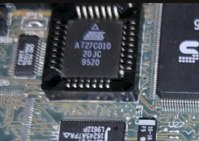
Issues Extracting Phoenix BIOS

Using this entry to avoid anyone else wasting their time trying to extract/backup a Phoenix BIOS using the Phoenix branded tools available on the web.

(Please note this does not apply to 'Phoenix-Award')

After obtaining each version from:
https://www.wimsbios.com/phoenixflasher.jsp#gsc.tab=0

Its been disappointing to realise that the official utilities require you to have a 'new' valid bios file before it will allow you to proceed to the back up step (regardless if you have selected back up only or backup and flash) .

It seems the ' backup bios rom and then exit' use case wasn't considered.

Exploring the command line interface of both DOS versions and Windows versions suggests these switches should help achieve this (they dont!)

/BU <filename>
and
/RO <filename>

/BU is only really to determine the name of the backup file - before it tries to flash.

/RO is used to extract the one of the components stored within the bios backup file ie the flash data component. Correction - now that i have random bios file, it appears this switch is actually trying to save the internal bios to a specified file (but not write a new bios to the internal flashrom)

The bios backup files supplied by vendors look to contain 'data to flash' + 'information on how to flash it'. The RO switch looks to be more about extracting the flash part from a given bios package file. This is based on my reading of Phoenix utilities user guide found on the same site.

So now it looks like I'll need to find an external hardware bios reader thats compatible and maybe a few spare bios eeproms.

Also worth mentioning:
- behaviour of both windows and dos versions is the same (with switches and both requiring an input file)
- not a great deal of visual difference between the windows ones (although take note some dlls are missing in some windows packages but can be found in other ones)
- while the windows editions won't work in w95, they will work in win98 and newer.
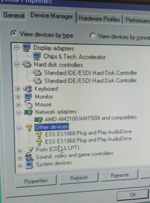
- on windows nt 4, it seem to keep giving dll errors 'kept looking for powrprof.dll '

Haven't tried any other 3rd party bios tools As cant find any that support socket 3 era Phoenix bios but I think its likely safer to use.an external reader now

UPDATE #1
I found a random BIOS.WHP on the net that at least gets me past the Phoenix 'need' a bios file requirements of phlasher16

Filename
BIOS_WPH.zip
File size
603.55 KiB
Downloads
35 downloads
File license
Fair use/fair dealing exception

This was found in a CRISDISK package, which Ive since learnt is a method to rescue a bad bios flash on some motherboards ('Crisis Disk BIOS Recovery Boot Block') .
I've included it with this post, in case anyone body needs to use it to try and make a backup of their internal bios - but becareful!

While it got me through the first error, and enabled me to move to the stage of extracting the SBC's internal bios via phlasher16 - that stage of the phlasher16 crashed / froze the pc. So no luck for backing up the bios for now.
Have ordered a hardware device to see if i can read the rom (which is still a few weeks away)

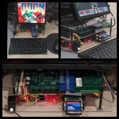
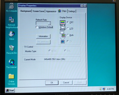
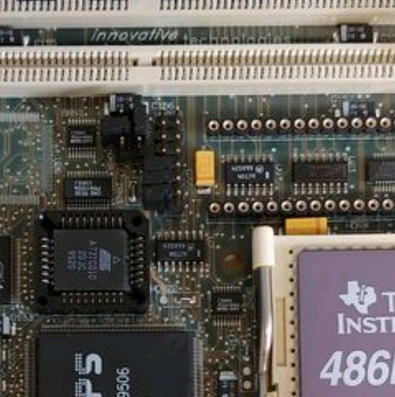
Windows Performance on 486
Also to summarise my experience of playing around with installing windows on this 486 SBC (with 32MB ram, video card with 512KB ram)

Windows 95b = great /zippy
Windows 98 SE = sluggish / terribly slow /but usable
Win NT4 = works well similar experience to w95

So as per other posts on vogons - wouldnt go later than w95 on a 486.

Last edited by dekkit on 2023-02-25, 12:09. Edited 2 times in total.

Reply 29 of 66, by rasz_pl

User metadata
Rank l33t
Rank
l33t

just try uniflash, third party flashing tools dont need to support particular bios vendor. At worst they need chipset support in case its something never with security/locking mechanisms.

Open Source AT&T Globalyst/NCR/FIC 486-GAC-2 proprietary Cache Module reproduction

Reply 30 of 66, by dekkit

User metadata
Rank Member
Rank
Member
rasz_pl wrote on 2023-02-18, 18:39:

just try uniflash, third party flashing tools dont need to support particular bios vendor. At worst they need chipset support in case its something never with security/locking mechanisms.

Thanks will give that a go and report back.

Reply 31 of 66, by dekkit

User metadata
Rank Member
Rank
Member
rasz_pl wrote on 2023-02-18, 18:39:

just try uniflash, third party flashing tools dont need to support particular bios vendor. At worst they need chipset support in case its something never with security/locking mechanisms.

arghh I received the following error when using the switch "-save bios.bin":
"PCI Bus not found or not responding" 🙁

Not sure if there is a specific switch i can try but i was able to successfully store the CMOS settings.

FYI - details from the boot screens
PhoenixBIOS v4.04
Copyright 1984-94
BIOS v 1.0.6

any other suggestions worth exploring?

Reply 32 of 66, by rasz_pl

User metadata
Rank l33t
Rank
l33t

uniflash doesnt support your chipset directly
https://github.com/applerom/runiflash/blob/c6 … FLASH.PAS#L1909

-BASE xxxxx Set ROM Base to address xxxxx (at least 5 hex digits)
-BASE: Set ROM base address manually and allow running without PCI bus.

Open Source AT&T Globalyst/NCR/FIC 486-GAC-2 proprietary Cache Module reproduction

Reply 34 of 66, by dekkit

User metadata
Rank Member
Rank
Member

Looking closer at photos of the SBC hardware, I started looking for bios ic to locate a datasheet in support of finding address ranges etc.

Screenshot_20230221-120601~2.png
Filename
Screenshot_20230221-120601~2.png
File size
800.19 KiB
Views
1007 views
File license
CC-BY-4.0

BIOS IC= Atmel 27c010

What is interesting is this IC is a ' one time programmable ' or OTP - even if I did extract the bios via software, I would still need a kit to burn the modified bios with CRT settings onto a new atmel ic anyway.

Suspect these SBC boards came out as part of a kit with a packed in screen /keyboard.

UPDATE #1
Tried a few values hex values found here and still no dice with uniflash

http://philipstorr.id.au/pcbook/book1/post.htm

The BIOS ROM started at FE000hex and extended to FFFFFhex.

In addition to the POST and its associated setup and bootstrap routines, the BIOS ROM also contains a series of Basic Input Output Services that provide services to DOS and to application software.

The BIOS ROM in the PC/AT computer, and in all modern Intel based computers, is a 64K byte ROM and occupies all the "F" region of memory, starting at F0000hex and extending to FFFFFhex. This is at the end of the first One Meg of address space.

Reply 35 of 66, by dekkit

User metadata
Rank Member
Rank
Member

Replacement BIOS EPROM AT27C010-20JC

In hunting around the online market stores (ebay/ali express) - ive noticed they typically stock:

AT27C010-15JC
AT27C010-45JC
AT27C010-90JC

Digging further into a collection of datasheets and googling to understand better - the '20JC' code is refering to 'Address to Output delay' which is measured in nano seconds (ns).

Its the time taken when requesting information from the bios to when it is delivered.

The code does not always translate to a specific nano second (as I incorrectly assumed '20JC' was the same as 20ns - it actually refers to 200ns !)

Ive reproduced the key part of the datasheet to help explain the difference:

Screenshot_20230221-223907~2.png
Filename
Screenshot_20230221-223907~2.png
File size
244.93 KiB
Views
968 views
File license
Fair use/fair dealing exception

From what ive read - its ok have lower ns response value (although I will aim for a bios chip with a lower but near value) ie AT27C010-15JC which is 150ns.

Reply 37 of 66, by pentiumspeed

User metadata
Rank l33t
Rank
l33t
dekkit wrote on 2023-02-21, 12:05:
Replacement BIOS EPROM AT27C010-20JC […]
Show full quote

Replacement BIOS EPROM AT27C010-20JC

In hunting around the online market stores (ebay/ali express) - ive noticed they typically stock:

AT27C010-15JC
AT27C010-45JC
AT27C010-90JC

Digging further into a collection of datasheets and googling to understand better - the '20JC' code is refering to 'Address to Output delay' which is measured in nano seconds (ns).

Its the time taken when requesting information from the bios to when it is delivered.

The code does not always translate to a specific nano second (as I incorrectly assumed '20JC' was the same as 20ns - it actually refers to 200ns !)

Ive reproduced the key part of the datasheet to help explain the difference:
Screenshot_20230221-223907~2.png

From what ive read - its ok have lower ns response value (although I will aim for a bios chip with a lower but near value) ie AT27C010-15JC which is 150ns.

EPROM and EEPROMs you know better they are not like cache chips speeds, they are slow as always. Above 300ns and less. Quickest one I seen is about 70ns.

Cheers,

Great Northern aka Canada.

Reply 38 of 66, by dekkit

User metadata
Rank Member
Rank
Member
nuno14272 wrote on 2023-02-22, 13:41:

Hello, di you find the jumpers for 40mhz fsb ? to give you the 80mhz cpu

Not yet! They are all 'somewhere around here' amongst the bunch of jumpers:

Screenshot_20230223-211135~2.png
Filename
Screenshot_20230223-211135~2.png
File size
987.62 KiB
Views
878 views
File license
CC-BY-4.0

I vaguely recall reading that 40mhz can be problematic for some ram timings etc.

Given the lack of info on the board - im still a bit nervous about messing them, burning out the CPU with an incorrect voltage etc etc .

Given it would be for an extra 14mhz, I'm comfortable with dx2-66 for the time being.

Reply 39 of 66, by dekkit

User metadata
Rank Member
Rank
Member

Played around with "Navr til Software System Information" this weekend at least managed to extract / read all(?) of the bios information into a file - was expecting 128KB based on other posts i've read - so will need to check this.
It crashed on the IDE scan (maybe something with the CF cards i'm using - so i needed to use switch "- safe" for safe mode.

Link: https://www.vogonsdrivers.com/getfile.php?fil … 842&menustate=0

BIOS Extract
1 x BIOS = BIOS.ROM (64KB) - see the later post using a T48 Programmer to extract the AT27C10 rom.
1 x VGA bios = V_BIOS.VBI (32KB) - this is viewable in a hex editor.

Filename
BIOS_VGABIOS.zip
File size
65.46 KiB
Downloads
38 downloads
File license
Fair use/fair dealing exception

Note:
- the phoenix flashers don't like these files (ie saying invalid files), so i've only had a quick sift through via a hex editor.
- one bios tool reported the VGA address range to be "C00h - c7ffh " - so will need to validate that some how
- Id still like to use a hardware bios /eprom reader to make sure I've extracted all the information correctly.

The goal at this stage is to try and force CRT mode only in the bios - not sure how achievable but i have found some OEM tools for the chips video card which should hopefully help.

Last edited by dekkit on 2023-03-18, 13:56. Edited 2 times in total.