VOGONS


Reply 120 of 240, by CalamityLime

User metadata
Rank Member
Rank
Member

🤷‍♂️

That'll probably do, I called it "SS7 muRata vrm" since I don't know what else to call it. If you have a better suggestion, let us know.
Maybe something tying it to soyo boards since they seem to have commonly have the came vrm heatsink that I'm using as a reference; "Soyo SS7 upgrade" maybe?

I'm too tired to think of something good.

-Lime

Attachments

Be Happy, it's only going to get worse.
- Projects
Limes Strange 3D models
USB-2-232

Reply 121 of 240, by Sphere478

User metadata
Rank l33t++
Rank
l33t++

I'm thinking about going a simpler direction with the voltage interposer. very curious how this works out. I love how it uses the heatsink holes. Perfect!

Sphere's PCB projects.
-
Sphere’s socket 5/7 cpu collection.
-
SUCCESSFUL K6-2+ to K6-3+ Full Cache Enable Mod
-
Tyan S1564S to S1564D single to dual processor conversion (also s1563 and s1562)

Reply 122 of 240, by pentiumspeed

User metadata
Rank l33t
Rank
l33t
CalamityLime wrote on 2022-06-19, 06:48:
🤷‍♂️ […]
Show full quote

🤷‍♂️

That'll probably do, I called it "SS7 muRata vrm" since I don't know what else to call it. If you have a better suggestion, let us know.
Maybe something tying it to soyo boards since they seem to have commonly have the came vrm heatsink that I'm using as a reference; "Soyo SS7 upgrade" maybe?

I'm too tired to think of something good.

-Lime

What is the DC DC converter module you are using to make this VRM?

Cheers,

Great Northern aka Canada.

Reply 123 of 240, by CalamityLime

User metadata
Rank Member
Rank
Member
pentiumspeed wrote on 2022-06-19, 17:35:

What is the DC DC converter module you are using to make this VRM?

Cheers,

The plan is to use a OKL2-T/12
It claims to support 12 amps which would be a tad tight for the most power hungry of socket 7 cpus but honestly, I think it would still be fine.

Here's a mouser link https://www.mouser.ie/ProductDetail/580-OKL2-T-12-W12N2C

Be Happy, it's only going to get worse.
- Projects
Limes Strange 3D models
USB-2-232

Reply 124 of 240, by CalamityLime

User metadata
Rank Member
Rank
Member

I done a little recalculating with the resistors and I got a larger list of supported voltages with one less resistor. The text is a bit small which is a shame, not sure how to restructure the table to be more readable.
It would be handy with there was an easy scale option in kicad 😐

Here's hoping I actually read the spec sheet right!

Attachments

Be Happy, it's only going to get worse.
- Projects
Limes Strange 3D models
USB-2-232

Reply 125 of 240, by CalamityLime

User metadata
Rank Member
Rank
Member

Alright, I think that's it.

I think I have everything wired in correctly at the moment. Traces are as beefy as I can make them, foot prints all seem right, I think everything can be hand soldered fairly easily, triple checked the resistor switch map thing.
If anyone is up for looking at it to see if anything is wrong, I'd appreciate it. I just want to go over the datasheet for the murata module again and if I have things structured correctly. Time for a break at the moment and I'll return to it later.

EDIT: I did hastily make a 3d model of the murata module, hopefully it shows up in the 3d viewer.


Not a finalised release
Just to clarify, I don't consider this done yet and it is not to be considered working yet.

Attachments

Be Happy, it's only going to get worse.
- Projects
Limes Strange 3D models
USB-2-232

Reply 126 of 240, by CalamityLime

User metadata
Rank Member
Rank
Member

I decided to add a input filter cap. The value of the cap doesn't really matter too much, something like 22uf -> 47uf should be fine.

It does look like it's in a really awkward place but I have to make sure nothing is interfering with pin headers, the sides of the heatsink are thick so there's plenty of clearance for resistors and caps.
I went over the datasheet for the murata module and I'm pretty sure I have everything right.

-lime

Attachments

Be Happy, it's only going to get worse.
- Projects
Limes Strange 3D models
USB-2-232

Reply 127 of 240, by pentiumspeed

User metadata
Rank l33t
Rank
l33t

Always derate the amps or watts by certain % for headroom if datasheet did not specify derating. Say you have this module rated up to 12 amps, I call this up to 10 amps times 2.0V, 20W total, For 3.3V, this is 33W. Good to include a jumper if you can to get it to 3.5V or so for some CPUs. Efficiency goes up with higher input voltage which is in your case it takes 12V which is included in the VRM module pinout, at 5V input, it might get bit more warmer.

This is why I searched and purchased few modules that is rated for 16A max so I allow for my similar projects to have 14A and another module rated for 30A (has two inductors).

Cheers,

Great Northern aka Canada.

Reply 128 of 240, by CalamityLime

User metadata
Rank Member
Rank
Member
pentiumspeed wrote on 2022-06-19, 23:32:

Always derate the amps or watts by certain % for headroom if datasheet did not specify derating. Say you have this module rated up to 12 amps, I call this up to 10 amps times 2.0V, 20W total, For 3.3V, this is 33W. Good to include a jumper if you can to get it to 3.5V or so for some CPUs. Efficiency goes up with higher input voltage which is in your case it takes 12V which is included in the VRM module pinout, at 5V input, it might get bit more warmer.

This is why I searched and purchased few modules that is rated for 16A max so I allow for my similar projects to have 14A and another module rated for 30A (has two inductors).

Cheers,

Fair point and I have been keeping that in mind some at least some bit.
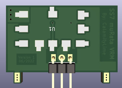
My knowledge of dc/dc modules is very limited and I'm very sceptical of many dc/dc modules, the only brand I know in the scene that's well regarded is muRata. They have a 12amp module that fits where I need it and I've seen in another thread that the 20amp module was being used in a similar scenario.

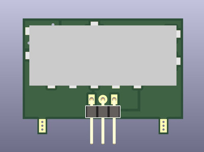
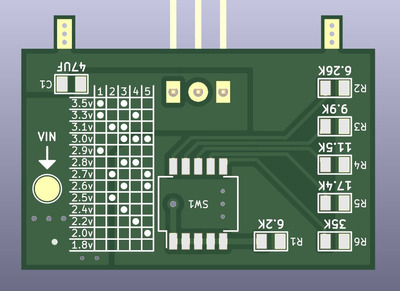
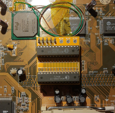
This is aimed to my board that has 2 VRM units, one with a large heatsink that steps 5v down to 3.5ish or 3.3ish, then a much smaller second one for dual voltage cpus that steps the voltage from the first vrm down to core voltage.
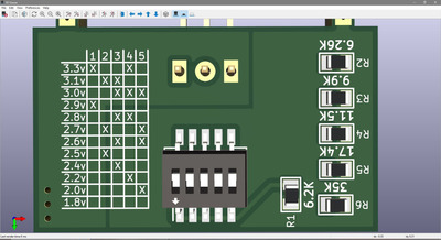
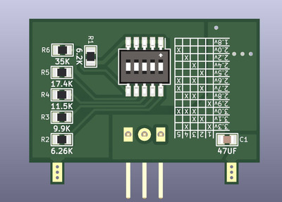
I can set the second vrm to be bypassed so the first vrm handles the 3.5ish, though this can do 3.5 with switches 1 & 3.

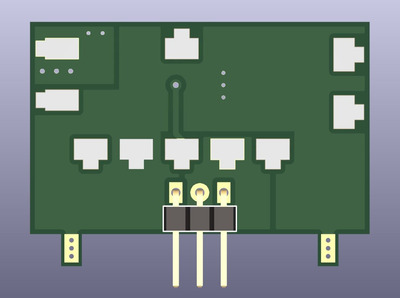
There is also a jumper on the back of the smaller vrm that lets me switch between 5v and output of vrm 1 for the input of vrm2. As a consequence I could pump 12 v in through there and I'm toying with adding like a solder pad or something to this device as a shortcut to add 12v. It's a small board, finding space is getting difficult. I wrote 5v on the schematic because the original vrm circuitry that used linear regulators ran off of the 5v rail.

If it isn't obvious, this module is aimed to replace vrm2 (the smaller vrm) that generates the core voltage.

Now onto numbers and this is where things get a little self-centered;
The most power hungry CPU that I ordered and will use if everything works, is an AMD k6 500mhz. I might try others just for fun but I'm assuming that this k6 will live in the board.
Going off of the data found on CPU world, the CPU is a 2.2v CPU that consumes a max of 20.75 watts, that works out to just under 9.5 amps which is just a hair under the 10amp ceiling that you seem to be suggesting. This would be pushing the CPU as hard as it can go which is something I personally wouldn't be doing much of. For retro computing I just want something with a bit more kick than my 486 100mhz CPU .

For 2.0v cpus that want over 10amps, you'd definitely want to look at the 20 amp unit at least, though I'd worry about the traces on the actual motherboard being an issue if the stock vrm couldn't deliver that kind of power.

I think that addresses everything, thanks for your comment!
-Lime

PS: I'm not sure I can fit the 20amp version of this module but I might give it a try.

Be Happy, it's only going to get worse.
- Projects
Limes Strange 3D models
USB-2-232

Reply 129 of 240, by CalamityLime

User metadata
Rank Member
Rank
Member

Rough edits to fit the 20amp version of the module.

The board is wider and taller as a result, it may still fit albeit a bit tight.

Attachments

Be Happy, it's only going to get worse.
- Projects
Limes Strange 3D models
USB-2-232

Reply 130 of 240, by CalamityLime

User metadata
Rank Member
Rank
Member

Alrighty!

I think that's done.
I added a test pad for an alternative way of adding a vin voltage to the murata module. I know it seems weird but it's just there as an experiment. Probably best to cover it with tape if it's not being used.
Once again I made a rough 3d model of the murata module, hopefully it'll show up in the 3d viewer.

What do people think?
I kinda grinded this board out so I can order some stuffs from PCBway. I think it's good enough to order though I'd like to look at it with fresh eyes first.


Not a finalised release
Just to clarify, I don't consider this done yet and it is not to be considered working yet.

-Lime

Attachments

Be Happy, it's only going to get worse.
- Projects
Limes Strange 3D models
USB-2-232

Reply 131 of 240, by Sphere478

User metadata
Rank l33t++
Rank
l33t++
CalamityLime wrote on 2022-06-20, 05:40:
Alrighty! […]
Show full quote

Alrighty!

I think that's done.
I added a test pad for an alternative way of adding a vin voltage to the murata module. I know it seems weird but it's just there as an experiment. Probably best to cover it with tape if it's not being used.
Once again I made a rough 3d model of the murata module, hopefully it'll show up in the 3d viewer.

What do people think?
I kinda grinded this board out so I can order some stuffs from PCBway. I think it's good enough to order though I'd like to look at it with fresh eyes first.


Not a finalised release
Just to clarify, I don't consider this done yet and it is not to be considered working yet.

-Lime

image.jpg
Filename
image.jpg
File size
1.44 MiB
Views
540 views
File license
Public domain
image.jpg
Filename
image.jpg
File size
1.94 MiB
Views
540 views
File license
Public domain

The reduced cross section bugs me. :p looks good though. I’m not familiar with the schematic though so no comments on that yet.

I know this will mess everything up, but remember how you made the rear bracket? I'm thinking if you wanted to, you could make the dip face upward with a T pcb setup.

Just throwing ideas out. I don't notice anything blaringly obvious from here. But when you are the one creating it you stare at it for hours and notice all sorts of things! 😀

Sphere's PCB projects.
-
Sphere’s socket 5/7 cpu collection.
-
SUCCESSFUL K6-2+ to K6-3+ Full Cache Enable Mod
-
Tyan S1564S to S1564D single to dual processor conversion (also s1563 and s1562)

Reply 132 of 240, by CalamityLime

User metadata
Rank Member
Rank
Member

I have ordered the boards. I changed a little about them before ordering.
First order from PCBway, so it'll be nice to compare them to JLC

EDIT: A T board style thing like suggest would be handy alright. I'd just have to make the board bigger. The datasheet for the murata module seems to highly recommend having nothing under the module. I have a single via because I have no-where else to put it, tenting should make it a non issue.

EDIT: While I was at it i did order the RTC hat board and the ps2 break out board that I made to fit into a serial port hole on the pc case.
I look forward to seeing PCBways work.

Attachments

Be Happy, it's only going to get worse.
- Projects
Limes Strange 3D models
USB-2-232

Reply 133 of 240, by Sphere478

User metadata
Rank l33t++
Rank
l33t++

San I see the ps2 thing? sounds interesting.

Sphere's PCB projects.
-
Sphere’s socket 5/7 cpu collection.
-
SUCCESSFUL K6-2+ to K6-3+ Full Cache Enable Mod
-
Tyan S1564S to S1564D single to dual processor conversion (also s1563 and s1562)

Reply 134 of 240, by CalamityLime

User metadata
Rank Member
Rank
Member
Sphere478 wrote on 2022-06-22, 03:17:

San I see the ps2 thing? sounds interesting.

Theres the kicad files.

I mentioned it a while ago, it's a 2 part thing. The PCB with the ps2 port and headers & a 3d printed part to mount it to the case.
It was just all made together to fit in a blank serial port I have spare.

Made it for the soyo, since it has a spot for a ps2 mouse but the case I have does not have a ps2 port hole.

Attachments

Be Happy, it's only going to get worse.
- Projects
Limes Strange 3D models
USB-2-232

Reply 135 of 240, by CalamityLime

User metadata
Rank Member
Rank
Member

the tag ram mod board arrived!

Attachments

Be Happy, it's only going to get worse.
- Projects
Limes Strange 3D models
USB-2-232

Reply 136 of 240, by Sphere478

User metadata
Rank l33t++
Rank
l33t++
CalamityLime wrote on 2022-06-23, 13:28:

the tag ram mod board arrived!

Damn, they made that one upside down…

So when are ya gonna fire it up? 😀

Sphere's PCB projects.
-
Sphere’s socket 5/7 cpu collection.
-
SUCCESSFUL K6-2+ to K6-3+ Full Cache Enable Mod
-
Tyan S1564S to S1564D single to dual processor conversion (also s1563 and s1562)

Reply 137 of 240, by CalamityLime

User metadata
Rank Member
Rank
Member
Sphere478 wrote on 2022-06-23, 13:30:
CalamityLime wrote on 2022-06-23, 13:28:

the tag ram mod board arrived!

Damn, they made that one upside down…

So when are ya gonna fire it up? 😀

I suppose when my cpus arrive

Be Happy, it's only going to get worse.
- Projects
Limes Strange 3D models
USB-2-232

Reply 138 of 240, by CalamityLime

User metadata
Rank Member
Rank
Member

I assembled one PCB just to see how it looks and I think it came out well!

Attachments

Be Happy, it's only going to get worse.
- Projects
Limes Strange 3D models
USB-2-232

Reply 139 of 240, by Sphere478

User metadata
Rank l33t++
Rank
l33t++

That actually does look pretty good!

I think it’s gonna work also, seems like you guys got it all figured out properly.

Suggest super glue for wires.

You can route them like traces with no tape.

Hot air can pull them up later if you are careful.

Sphere's PCB projects.
-
Sphere’s socket 5/7 cpu collection.
-
SUCCESSFUL K6-2+ to K6-3+ Full Cache Enable Mod
-
Tyan S1564S to S1564D single to dual processor conversion (also s1563 and s1562)