VOGONS


Fixing up a Soyo SY-5TF Socket 7 Motherboard

Topic actions

Reply 220 of 240, by CalamityLime

User metadata
Rank Member
Rank
Member

Hello there!

So the installation didn't go great.
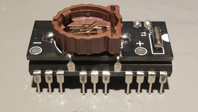
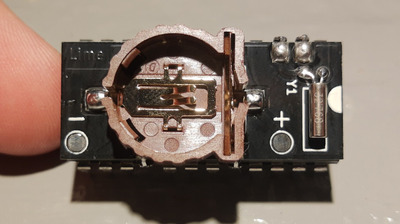
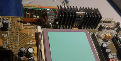
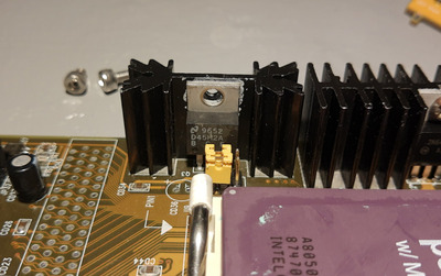
The legs of the PCB were too far apart so I cut the legs off and tombstoned the PCB to the pad under the original heatsink.
Other than that, things went smoothly.

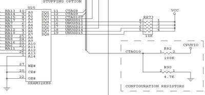
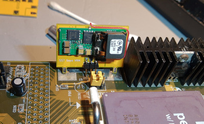
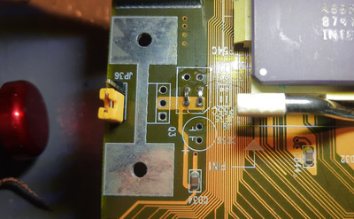
I removed a jumper block from the front of the PCB and replaced it with hard jumpers so the CPU vcore is powered from the murata and only the murata now. I added JP36 which changes the input voltage between 5v from the PSU and 3.3v from the CPU io VRM module. Currently it is now set to 5v.

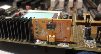
The board does fit decently well and the dip switch is easily available.

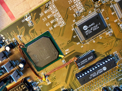
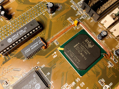
Using the Pentium MMX cpu and setting the murata to 2.8V with dip 1, I booted the PC expecting the worst but it posted and booted!
Huzzah, it works.

As a fun test I kept air flow away from the large IO VRM heatsink that would get so hot it was very uncomfortable to touch before and after 20 mins of sitting idle, the heatsink was just slightly warmer than the PC case itself.
So that means less energy being dumped off as heat.

This post is a bit all over the place I know but this is still initial thoughts. I'll probably structure this information in a future post when I try the super socket 7 k6 cpu on the mobo.
Wish me luck!

-Lime.

Attachments

Be Happy, it's only going to get worse.
- Projects
Limes Strange 3D models
USB-2-232

Reply 221 of 240, by Sphere478

User metadata
Rank l33t++
Rank
l33t++

Freakin awesome, i guess it goes without saying that there will be a version 2 of the pcb. 😀

What cpus do you have again? Do you have a 2+ 570?

You should grab these:

Tillamook 266 sl2z4 or 233 sl2z3
Any old cyrix mII 2.2v (specifically 2.2v, it’s the 433gp core)
And a k6 2+ to mod.
If you are feeling adventurous a rise 266 is fun also.

Sphere's PCB projects.
-
Sphere’s socket 5/7 cpu collection.
-
SUCCESSFUL K6-2+ to K6-3+ Full Cache Enable Mod
-
Tyan S1564S to S1564D single to dual processor conversion (also s1563 and s1562)

Reply 222 of 240, by CalamityLime

User metadata
Rank Member
Rank
Member

I finally put one of the DS128x hats together.
it came out decent for a quickly thrown together board. Might add a mirrored set of pads on the bottom so the user can solder the dip legs for the battery on the underside of the PCB vs under the battery holder like I did here.

Attachments

  • 2.jpg
    Filename
    2.jpg
    File size
    243.37 KiB
    Views
    658 views
    File license
    CC-BY-4.0
  • 1.jpg
    Filename
    1.jpg
    File size
    277.74 KiB
    Views
    658 views
    File license
    CC-BY-4.0

Be Happy, it's only going to get worse.
- Projects
Limes Strange 3D models
USB-2-232

Reply 223 of 240, by Sphere478

User metadata
Rank l33t++
Rank
l33t++

Very nice

Sphere's PCB projects.
-
Sphere’s socket 5/7 cpu collection.
-
SUCCESSFUL K6-2+ to K6-3+ Full Cache Enable Mod
-
Tyan S1564S to S1564D single to dual processor conversion (also s1563 and s1562)

Reply 224 of 240, by CalamityLime

User metadata
Rank Member
Rank
Member

Quick update,

The DS128X hat worked a treat even with a cheap ali express DS12885.

I also did install the AMD k6-2 with the voltage mod and it does work just fine. I did finally order and receive the new revision of the ss7 VRM board thing. It does look nice.
The system clock of 66mhz is a bottle neck but eh, no biggie.
Maybe I should update the board to work similar to what necroware made ages ago. The OKI module really works a treat, I'm not even getting any coil whine.

Be Happy, it's only going to get worse.
- Projects
Limes Strange 3D models
USB-2-232

Reply 225 of 240, by Sphere478

User metadata
Rank l33t++
Rank
l33t++

Gonna get a 3+? 😀

So the modules should work good for the interposer?

Sphere's PCB projects.
-
Sphere’s socket 5/7 cpu collection.
-
SUCCESSFUL K6-2+ to K6-3+ Full Cache Enable Mod
-
Tyan S1564S to S1564D single to dual processor conversion (also s1563 and s1562)

Reply 226 of 240, by CalamityLime

User metadata
Rank Member
Rank
Member
Sphere478 wrote on 2022-10-11, 03:59:

Gonna get a 3+? 😀

So the modules should work good for the interposer?

I don't think I'll get a 3+ for this mobo, is there really even a point? maybe with a higher end one yeah but not the one I have.

And the OKI modules should work fine. I've had my machine on for a few hours one day trying to get audio drivers working and there was no issues with it all.
I was thinking though, would it benefit from a low ESR cap or a poly cap or two just for the CPU's that can take more juice? My mobo for example had only standard aluminium caps on it

Be Happy, it's only going to get worse.
- Projects
Limes Strange 3D models
USB-2-232

Reply 227 of 240, by majestyk

User metadata
Rank Oldbie
Rank
Oldbie

I was just looking at the VRMs, was the one with the small heatsink the one that was getting hot? This would be a design flaw since the one with the small heatsink is supposed to be responsible for the 3.3V I/O voltage where there´s only a tiny current and quite little heat dissipation.

Reply 228 of 240, by Sphere478

User metadata
Rank l33t++
Rank
l33t++
CalamityLime wrote on 2022-10-15, 14:01:
I don't think I'll get a 3+ for this mobo, is there really even a point? maybe with a higher end one yeah but not the one I have […]
Show full quote
Sphere478 wrote on 2022-10-11, 03:59:

Gonna get a 3+? 😀

So the modules should work good for the interposer?

I don't think I'll get a 3+ for this mobo, is there really even a point? maybe with a higher end one yeah but not the one I have.

And the OKI modules should work fine. I've had my machine on for a few hours one day trying to get audio drivers working and there was no issues with it all.
I was thinking though, would it benefit from a low ESR cap or a poly cap or two just for the CPU's that can take more juice? My mobo for example had only standard aluminium caps on it

Oh yeah, 400 mhz at 66 fsb I play sims and sim theme park on my tyan s1564D with a k6-3+ If you can do 83mhz it will clock to 500 mhz heck I’ve even played halo with lag on it. Radeon 7500 and a k6-3+ will really wake up a mobo like this.

Feipoa and I were talking about caps recently. He was thinking several caps of different values would be best but I was thinking that they would just all add and make one big cap anyway.

and higher capacitance and lower resistance the better but of course at some point there is a diminishing return.

Unsure which if us is more correct.

more capacatance and lower resistance can lead to large power on inrush. And also slow shutdown. But probably not a issue at the capacitances we are talking about.

Sphere's PCB projects.
-
Sphere’s socket 5/7 cpu collection.
-
SUCCESSFUL K6-2+ to K6-3+ Full Cache Enable Mod
-
Tyan S1564S to S1564D single to dual processor conversion (also s1563 and s1562)

Reply 229 of 240, by majestyk

User metadata
Rank Oldbie
Rank
Oldbie

A mainboard like the SY-5TF will not profit from larger/better caps performancewise.
It can be useful to prevent instabilities that can occur under a combination of certain conditions, like a power hungry CPU (K6-III), heavy I/O loads, suboptimal PSUs, layout and wiring weaknesses, transients caused by sudden load drops or rises.

It used to be best practice to use tantalum capacitors for filtering near the chipset, PCI-slots, memory slots and PSU connector to block high frequency noise and EMC troubles. You can still find them at the clock generator on later mainboards, since this is a delicate area under high frequency related aspects.
Since tantalum became increasingly expensive, manufacturers switched to regular and mostly cheapish electrolytics with poor ESR and impedance values.
Another way is to add a low impendance ceramic chip capacitor (10-100nF) to each electrolytic by soldering it directly between the pins at the soldering side of the PCB. This chip capacitor then will take care of very high frequency noise / transients far more efficient than the electrolytic could.
You can also find ceramic disc capacitors parallel to each electrolytic on early ASUS boards - same thing (and very prudent).
An array of parallel electrolytics of the same capacity also reduces ESR. If there are capacitors with different capacities working parallel - for example in the VRM circuitry - it´s a bad thing since there will be different currents for each cap and one of them will have to take most of the ripple current. This one will age faster than the others.

You must also observe the total capacity for each(!) single voltage rail, since there´s a limit the PSU can take. It´s defined in the ATX specifications. You cannot just have 30 x 1500µF at the 5V rail for example. Sometimes the (poor) capacities the manufacturer used are *not* due to saving costs but necessary to stay below the maximum total capacity.

Reply 230 of 240, by CalamityLime

User metadata
Rank Member
Rank
Member
majestyk wrote on 2022-10-15, 15:06:

I was just looking at the VRMs, was the one with the small heatsink the one that was getting hot? This would be a design flaw since the one with the small heatsink is supposed to be responsible for the 3.3V I/O voltage where there´s only a tiny current and quite little heat dissipation.

The large heat sink generated the 3.6 or 3.3 for io and single voltage cpus, the smaller heat sink generated the 2.odd voltage for dual votage cpu's. The small heatsink was feed off of the large one so the large one would get hottest really.
Since installing the OKI module where the small heatsink was, the large heatsink just makes the 3.3 for io and the OKI module generates the 2.2v from 5v for my AMD 2.
Neither get hot. I left the system on for a few hours just running some game benchmarks and getting audio drivers working. I couldn't feel any heat from either the OKI module or the large heatsink.

Be Happy, it's only going to get worse.
- Projects
Limes Strange 3D models
USB-2-232

Reply 231 of 240, by CalamityLime

User metadata
Rank Member
Rank
Member
majestyk wrote on 2022-10-15, 17:21:
A mainboard like the SY-5TF will not profit from larger/better caps performancewise. It can be useful to prevent instabilities […]
Show full quote

A mainboard like the SY-5TF will not profit from larger/better caps performancewise.
It can be useful to prevent instabilities that can occur under a combination of certain conditions, like a power hungry CPU (K6-III), heavy I/O loads, suboptimal PSUs, layout and wiring weaknesses, transients caused by sudden load drops or rises.

.....

You must also observe the total capacity for each(!) single voltage rail, since there´s a limit the PSU can take. It´s defined in the ATX specifications. You cannot just have 30 x 1500µF at the 5V rail for example. Sometimes the (poor) capacities the manufacturer used are *not* due to saving costs but necessary to stay below the maximum total capacity.

This is also a concern for the OKI module. The upper limit for higher ESR capacitance is very generous and the upper limit for low ESR capacitance is less generous. The OKI module does want some kind of low ESR cap for it's own noise regulation. I used a 47uf cap on the yellowboard and that seems to be within spec. The only reason I mentioned low ESR caps was because of a video by necroware where he was buying some low ESR caps and why he needed low ESR caps. It just made me wonder about boards like mine being made for much lower end socket 7 cpu's being forced to take higher end socket 7 cpus. Just a thought really.

Be Happy, it's only going to get worse.
- Projects
Limes Strange 3D models
USB-2-232

Reply 232 of 240, by majestyk

User metadata
Rank Oldbie
Rank
Oldbie

So they "cascaded" the two regulators. Some manufacturers did that to limit the heat disspation of the second VRM, but the drawback is that the 2nd VRM acts as a variable (instable) load at the output of the 1st VWM. This design is not first choice.
To improve / optimize the situation you can cut the connection between the output of VRM1 and the input of VRM2 and connect the latter directly to the 5V rail.

Reply 233 of 240, by CalamityLime

User metadata
Rank Member
Rank
Member
majestyk wrote on 2022-10-16, 17:52:

So they "cascaded" the two regulators. Some manufacturers did that to limit the heat disspation of the second VRM, but the drawback is that the 2nd VRM acts as a variable (instable) load at the output of the 1st VWM. This design is not first choice.
To improve / optimize the situation you can cut the connection between the output of VRM1 and the input of VRM2 and connect the latter directly to the 5V rail.

yeah, I've done that already. There was a spot behind the small VRM for a pin header to switch between the output for VRM1 and 5v for the input of VRM2

Be Happy, it's only going to get worse.
- Projects
Limes Strange 3D models
USB-2-232

Reply 234 of 240, by majestyk

User metadata
Rank Oldbie
Rank
Oldbie

While looking at my own SY-5TF I thought of an alternative approach to integrate the second TAG-RAM chip. Why not use the landings for the TAG-RAM besides the DIL TAG-Socket?
Most connections can be used since they are wired parallel to the first TAG chip.
So I cut the legs of the new TAG chip that mustn´t have contact with the PCB, added 5 x 10K SMD resistors at the unsused I/O ports (7:3), connected the common side to ground, removed the 10K resistor on the mainboard at the TIO10 pin of the MCH that pulls TIO10 up when there´s only 64MB cacheable area provided, added a 10K resistor directly at the new TAG chip between GND and I/O2 / pin13 (=TIO10) to pull the line down, soldered the new chip and made 3 wire connections to the TIO 10:8 pins.
That´s what it looks like:

alternative_ext1.JPG
Filename
alternative_ext1.JPG
File size
909.97 KiB
Views
457 views
File license
Fair use/fair dealing exception

This works perfectly and is a quick and dirty solution for HX mainboards that have the landings for another chip in the layout that is not intended to extend the existing TAG but for having a second possibility to populate one TAG chip (SOJ instead of DIL or vice versa).
Now the wires must be fixated so they don´t get hurt...

Last edited by majestyk on 2022-11-16, 18:40. Edited 1 time in total.

Reply 235 of 240, by Sphere478

User metadata
Rank l33t++
Rank
l33t++

Ooo very nice! I like it!

I think one step better would be using actual PCB for the wires and then little tiny jumpers to the chipset like a bodge board

Sphere's PCB projects.
-
Sphere’s socket 5/7 cpu collection.
-
SUCCESSFUL K6-2+ to K6-3+ Full Cache Enable Mod
-
Tyan S1564S to S1564D single to dual processor conversion (also s1563 and s1562)

Reply 236 of 240, by majestyk

User metadata
Rank Oldbie
Rank
Oldbie

Yea, if only boards were more standardised so we could make a little "bridge-pcb" for many models.
I fixated the wires in the meantime by using doublesided duct-tape between the wires and pcb and a layer of sellotape on top to cover the sticky surface.

alternative_ext3.JPG
Filename
alternative_ext3.JPG
File size
940.33 KiB
Views
436 views
File license
Fair use/fair dealing exception

The wires are safe now but I still need some seal for the soldering joints.
The requirement is that all of this is completely reversible if needed.

The resistors at the unused I/O lines are suggested as 10K pull-ups in the original Intel circuit diagram for 430HX mainboards, but in 95% of the cases where two TAG-RAMS are populated on mainboards or COAST modules these resistors do not exist.

unusedIO.JPG
Filename
unusedIO.JPG
File size
61.93 KiB
Views
427 views
File license
Public domain

Reply 237 of 240, by Sphere478

User metadata
Rank l33t++
Rank
l33t++

I experimented with using super glue to hold wires like that. With some heat (and a breathing mask) it is reversible.

I was figuring a custom board for each and every board.

Technically, you could probably use a interposer to the chipset and the tag chip on the bodge board can’t get cleaner than that

Sphere's PCB projects.
-
Sphere’s socket 5/7 cpu collection.
-
SUCCESSFUL K6-2+ to K6-3+ Full Cache Enable Mod
-
Tyan S1564S to S1564D single to dual processor conversion (also s1563 and s1562)

Reply 238 of 240, by CalamityLime

User metadata
Rank Member
Rank
Member

Nice. Definitely lower profile and more discreet than the PCB I made. I'd still be interested in updating that to use smd parts.
But since you have the same soyo, mod that bios and toss in an OKL module for the CPU vcore, have some fun.

All the effort we go through just because motherboard makers couldn't be bothered to run 3 traces.

Be Happy, it's only going to get worse.
- Projects
Limes Strange 3D models
USB-2-232

Reply 239 of 240, by majestyk

User metadata
Rank Oldbie
Rank
Oldbie

The Soyo SY-5TF is a very nice board otherwise. To my surprise I found the cooling of the VRMs - at least when a regular CPU cooler is used - to be far more effective than I expected. The build quality is flawless and everything is designed with care.

Probably they (product managers) thought it wasn´t worth adapting the layout for a few years to come before the next mainboard generation took over.
But technically it´s a kind of "Fake Cache". 512K L2 cache are being reported by BIOS, 512MB RAM are supported and the HX chipset was promoted as being capable of caching all that RAM. But in fact it was reduced to the FX/VX level.