Reply 20 of 37, by butjer1010
rasz_pl wrote on 2022-07-08, 18:06:did you mean 1 long 2 short? […]
butjer1010 wrote on 2022-07-08, 13:53:without VGA board also beeps, but 1 long and 4 short beeps
did you mean 1 long 2 short?
butjer1010 wrote on 2022-07-08, 13:53:I tried put the vga in 8-bit slot, same result, same picture on monitor.
🙁 such a nice and convenient theory disproved
butjer1010 wrote on 2022-07-08, 13:53:I get 3 leds flash on keyboard when i turn on the computer, but nothing happens when i press any of "locks" when garbled screen shows up.
means bios crashes/gets stuck
post codes and order of initialization: http://mrbios.com/techsupport/award/postcodes.htm [AMI New BIOS; 06/06/92-08/08/93]
must be hanging somewhere between 2C and 2D? hmm how is the 5V on ISA slot? lack of proper power would make VGA draw parasitic power thru data pins and act weirdWhat happens when you do a hardware reset using S1 reset jumper?
Off the wall idea - try taking off JP2 jumper switching to mono monitor, with any luck this will force text mode 7 with different base address and attribute meaning, and produce different picture
poke carefully at all the 82C495XLC chipset pins with a toothpick to check if there arent any loose
Im running out of ideas, deeper diagnosing would require some tools (any of: post card, eprom flasher, logic analyser)
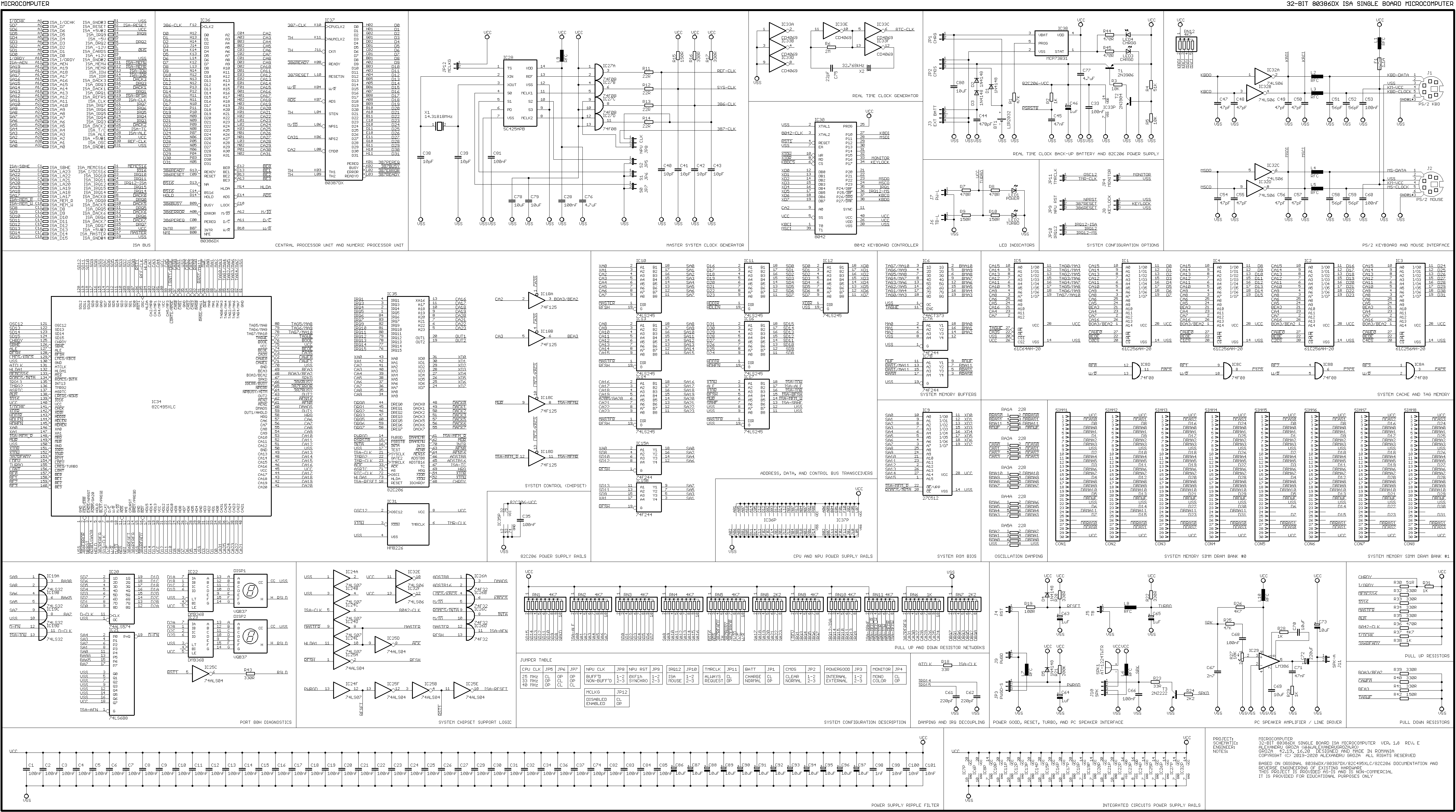
PS diagram of reverse engineered board on this chipset https://alexandrugroza.ro/microelectronics/sy … c-schematic.png sadly modular and not pdf , but still great resource. You can see where all the 244/245 buffers required for proper ISA operation connect
did you mean 1 long 2 short?
-actually, 2 very short beeps, and after one second 8 short beeps more???
What happens when you do a hardware reset using S1 reset jumper?
-PC restarts 😀, and broken screen again 😀
try taking off JP2 jumper switching to mono monitor, with any luck this will force text mode 7 with different base address and attribute meaning, and produce different picture
-same result without JP2 jumper
poke carefully at all the 82C495XLC chipset pins with a toothpick to check if there arent any loose
-today i tried to "fix" possible cold solder joints with flux and hot air, nothing has changed. I could try with toothpick, but i'm pretty sure that if there was any bad solder joints before, now i have fixed them.
hmm how is the 5V on ISA slot? lack of proper power would make VGA draw parasitic power thru data pins and act weird
-can You please spare me a time and tell which pins will give me possible 5V on ISA? Thanks in advance.
PS diagram of reverse engineered board on this chipset https://alexandrugroza.ro/microelectronics/sy … c-schematic.png sadly modular and not pdf , but still great resource. You can see where all the 244/245 buffers required for proper ISA operation connect
- i'm lost when i see this picture 😀 I'm not that good to understand all of this, i'm regular, maybe a little advanced user, but not a master like You 😀