VOGONS


Varta replacer

Topic actions

First post, by tabm0de

User metadata
Rank Member
Rank
Member

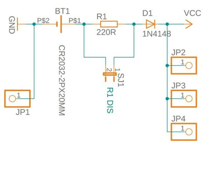
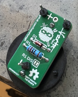
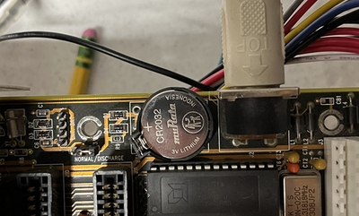
Just wanted to be sure as i never uses a "varta" replacer, i build one from https://github.com/RetroNynjah/Varta-Replacer.

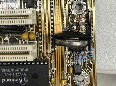
I did check that there is no connection between the plus line on the board to the battery holders plus side.

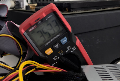
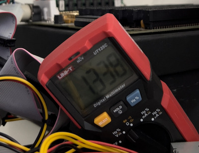
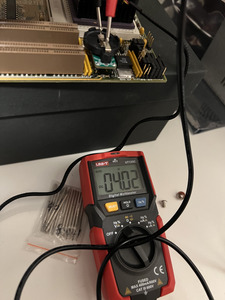
My only concern is that when the computer is on without battery i do still get value 3.8-4 when measure the +/- pools on the battery holder.
Shouldnt it be 0?

Attachments

Last edited by tabm0de on 2022-07-10, 22:21. Edited 1 time in total.

naa, nothing yet...

Reply 1 of 27, by Horun

User metadata
Rank l33t++
Rank
l33t++

No it should be about same voltage as the original Varta and 3.7-3.8v is standard. The diode keeps the board volts from trying to recharge the coin cell.

Hate posting a reply and then have to edit it because it made no sense 😁 First computer was an IBM 3270 workstation with CGA monitor. Stuff: https://archive.org/details/@horun

Reply 2 of 27, by imi

User metadata
Rank l33t
Rank
l33t
Horun wrote on 2022-07-10, 21:37:

No it should be about same voltage as the original Varta and 3.7-3.8v is standard. The diode keeps the board volts from trying to recharge the coin cell.

3.7V 3.0V is the nominal voltage for most lithium coincells, and while yes, regular NiCd/NiMh batteries have a nominal voltage of 1.2V (so 3.6V for a 3-cell barrel battery) that's not the entire story, you need to consider charge voltage and that barrel batteries on motherboards are usually kept charged at all times and how the charging circuits work with current limiting, that means they can be at 4.5/4.6V or even just 5V, sometimes maybe even higher.

though I'm surprised why there is any voltage present at all at the battery holder, shouldn't there be a diode to block that?

Last edited by imi on 2022-07-11, 08:42. Edited 1 time in total.

Reply 3 of 27, by Horun

User metadata
Rank l33t++
Rank
l33t++

Ok I thought you meant at the original Battery pins, not at the replacement battery.
The schematic calls for a diode in series with a 220 ohm resistor off the Coin V+ to the original battery + pin. My guess is that the diode in backwards...

Attachments

  • Image3.jpg
    Filename
    Image3.jpg
    File size
    26.52 KiB
    Views
    1232 views
    File license
    Fair use/fair dealing exception

Hate posting a reply and then have to edit it because it made no sense 😁 First computer was an IBM 3270 workstation with CGA monitor. Stuff: https://archive.org/details/@horun

Reply 4 of 27, by Sphere478

User metadata
Rank l33t++
Rank
l33t++

Someone made a external battery using 3xAAA in series for 4.5v I looked up the charging profile for the varta which I believe is 3s nicad or nimh and up to 4.5v is acceptable for that chemistry. So 4v may be charging voltage.

These boards may work with 3.3v also. This adapter might be designed to prevent charging.

Sphere's PCB projects.
-
Sphere’s socket 5/7 cpu collection.
-
SUCCESSFUL K6-2+ to K6-3+ Full Cache Enable Mod
-
Tyan S1564S to S1564D single to dual processor conversion (also s1563 and s1562)

Reply 5 of 27, by majestyk

User metadata
Rank Oldbie
Rank
Oldbie
imi wrote on 2022-07-10, 22:59:

3.7V is the nominal voltage for most lithium coincells, and while yes, regular NiCd/NiMh batteries have a nominal voltage of 1.2V (so 3.6V for a 3-cell barrel battery) that's not the entire story, you need to consider charge voltage and that barrel batteries on motherboards are usually kept charged at all times and how the charging circuits work with current limiting, that means they can be at 4.5/4.6V or even just 5V, sometimes maybe even higher.

though I'm surprised why there is any voltage present at all at the battery holder, shouldn't there be a diode to block that?

Regular LiSO2 cells (like the legendary CA2032) have a nominal (idle) voltage of 3.0V.
The only Lithium cell that has 3.7V is the LiSOCl2 (Lithium Thionyl Chloride) cell that´s very uncommon in consumer electronics.

Reply 6 of 27, by tabm0de

User metadata
Rank Member
Rank
Member
Horun wrote on 2022-07-10, 23:12:

Ok I thought you meant at the original Battery pins, not at the replacement battery.
The schematic calls for a diode in series with a 220 ohm resistor off the Coin V+ to the original battery + pin. My guess is that the diode in backwards...

Ye my thought also but it is added after the bord markings, but will try to reverse it.

Attachments

naa, nothing yet...

Reply 7 of 27, by imi

User metadata
Rank l33t
Rank
l33t

is your diode shorted by any chance?

don't just reverse it, it seems to be installed correctly.

majestyk wrote on 2022-07-11, 05:36:

Regular LiSO2 cells (like the legendary CA2032) have a nominal (idle) voltage of 3.0V.
The only Lithium cell that has 3.7V is the LiSOCl2 (Lithium Thionyl Chloride) cell that´s very uncommon in consumer electronics.

you're right, sorry I was thinking of rechargable lithiums ^^ ...which only makes it worse though 😁

Reply 8 of 27, by tabm0de

User metadata
Rank Member
Rank
Member

I have now changed diodes from ”1N4148-TAP” to ”1N4148” i guess ”tap” has something to do with it?

Now it just jumps random between mv and v which I understand is normal.

Attachments

naa, nothing yet...

Reply 9 of 27, by RandomStranger

User metadata
Rank Oldbie
Rank
Oldbie

What about LIR2032 lithium-ion batteries? They are 3.6V and rechargeable.
You can use them with regular CR2032 battery holder and being rechargeable suggest you don't need the charge blocking diode. Also these are like 2€/$
.
21627063457058_206.jpg

sreq.png retrogamer-s.png

Reply 11 of 27, by Sphere478

User metadata
Rank l33t++
Rank
l33t++
imi wrote on 2022-07-18, 10:34:

that's not how that works, you'd still need a dedicated charging circuit for them and not just connect them to one that is built for charging 3S NiCd batteries

What is the charging profile for those rechargeable coin cells? If it’s not exact, it may be close enough.

I believe nicad tops out at max 1.5 VPC (x3)

Sphere's PCB projects.
-
Sphere’s socket 5/7 cpu collection.
-
SUCCESSFUL K6-2+ to K6-3+ Full Cache Enable Mod
-
Tyan S1564S to S1564D single to dual processor conversion (also s1563 and s1562)

Reply 13 of 27, by Sphere478

User metadata
Rank l33t++
Rank
l33t++

So it sounds like it will work.

It mentions a cutoff voltage, so it sounds like it even has a basic integrated bms.

Which is pretty typical of many consumer cells.

Sphere's PCB projects.
-
Sphere’s socket 5/7 cpu collection.
-
SUCCESSFUL K6-2+ to K6-3+ Full Cache Enable Mod
-
Tyan S1564S to S1564D single to dual processor conversion (also s1563 and s1562)

Reply 14 of 27, by imi

User metadata
Rank l33t
Rank
l33t

what? no, those are the specs your curcuit has to adhere to, which on any board that wasn't designed for it obviously does not, if you discharge the cell below 3.0V you risk damaging it or reducing it's lifespan.
same obviously goes for overcharging it, there is no BMS in that cell.

Reply 15 of 27, by Sphere478

User metadata
Rank l33t++
Rank
l33t++

OP said they are getting 3.8 to 4 V constant when energized that should maintain the battery level and that is totally within safe range of that cell.

A Mechanically confined Lithium ion cell like that will probably survive a over discharge event as long as the BMS can be reset if it has one that is
I have actually seen some remarkably small single BMS boards, it is not impossible that that cell has one.In any case it doesn’t seem that the application is capable of over volting that cell which is the major concern Should a thermal event occur a cell of that size does not contain much thermal energy, enough to damage the motherboard possibly, probably enough to give you a burn if one of the pieces touches you but I highly doubt that it would come anywhere close to exiting a closed and sealed case and spreading fire But again the voltages seem within the range of the cell So such an event does not seem very likely

As long as OP is sure about the voltages that they are seeing it does seem like it should work

Concerns about current can be addressed with a inline resistor

Sphere's PCB projects.
-
Sphere’s socket 5/7 cpu collection.
-
SUCCESSFUL K6-2+ to K6-3+ Full Cache Enable Mod
-
Tyan S1564S to S1564D single to dual processor conversion (also s1563 and s1562)

Reply 16 of 27, by Sphere478

User metadata
Rank l33t++
Rank
l33t++

Might be looking into a project like this for a 486 board. what’s everyone’s opinion on this? Any updated user testimonials? What’s the best configuration?

Sphere's PCB projects.
-
Sphere’s socket 5/7 cpu collection.
-
SUCCESSFUL K6-2+ to K6-3+ Full Cache Enable Mod
-
Tyan S1564S to S1564D single to dual processor conversion (also s1563 and s1562)

Reply 17 of 27, by douglar

User metadata
Rank Oldbie
Rank
Oldbie
Sphere478 wrote on 2024-01-09, 22:56:

Might be looking into a project like this for a 486 board. what’s everyone’s opinion on this? Any updated user testimonials? What’s the best configuration?

I wish I have good answers.

Sometimes I use the flat holders, which are nice if you have the space on your board, but sometimes they overlap the edge of the board, block slots, and it's hard to get the diode in there.

Photo Jan 25 2024, 3 30 19 PM.png
Filename
Photo Jan 25 2024, 3 30 19 PM.png
File size
341.04 KiB
Views
356 views
File license
Public domain

The vertical holders are cheap and they take up less space, making it easier to fit the diode in there, but after you put the diode in, things can be fragile. I tried hot glue, but the tall coin slot has enough leverage to break free pretty easily.

Photo Jan 25 2024, 3 30 31 PM.png
Filename
Photo Jan 25 2024, 3 30 31 PM.png
File size
834 KiB
Views
356 views
File license
Public domain

So I don't know what to say.

Reply 18 of 27, by Sphere478

User metadata
Rank l33t++
Rank
l33t++

Tony359 recently did some work on one of my boards and was able to identify a diode I beleieve near by that when removed stopped 5v from reaching the battery terminals. And the rtc functioned properly with a 3.3v battery. So simply removed the diode and installed a coin cell holder.

Sphere's PCB projects.
-
Sphere’s socket 5/7 cpu collection.
-
SUCCESSFUL K6-2+ to K6-3+ Full Cache Enable Mod
-
Tyan S1564S to S1564D single to dual processor conversion (also s1563 and s1562)

Reply 19 of 27, by TheMobRules

User metadata
Rank Oldbie
Rank
Oldbie

Yeah, whenever possible disabling the charging circuit is a much better option if you're trying to use a CR2032. Not only a coin cell provides a lower voltage (3V) than the original barrel (3.6V) but also the extra diode you add will lower that voltage even further, which can result in the battery not being able to power the RTC or the memory that stores the CMOS settings.