Reply 20 of 27, by mockingbird
sardinesandwich wrote on 2022-09-17, 13:59:Filter capacitors:
200v 1000µF 85°c 50mm x 20.5mm diameter
https://www.digikey.jp/en/products/detail/nic … 2MELZ45/2540101
105°C capacitors: 50v 2.2µF 10.5mm x 4.5mm diameter 50v 4.7µF 10.5mm x 4.5mm diameter (probably, haven't removed this one yet) 5 […]
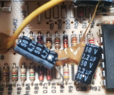
105°C capacitors:
50v 2.2µF 10.5mm x 4.5mm diameter
50v 4.7µF 10.5mm x 4.5mm diameter (probably, haven't removed this one yet)
50v 22µF 10.5mm x 4.5mm diameter (this was hidden under some wires)
10v 4700µF 32mm x 12mm diameter
10v 2200µF 23mm x 9mm diameter
16v 3300µF 32mm x 12mm diameter
10v 1000µF 18mm x 7.5mm diameter
16v 470µF 13mm x 8mm diameter
16v 100µF 10.5mm x 6mm diameter
1) 50v 2.2µF 10.5mm x 4.5mm diameter
2) 50v 4.7µF 10.5mm x 4.5mm diameter
3) 50v 22µF 10.5mm x 4.5mm diameter
4) 10v 4700µF 32mm x 12mm diameter
5) 10v 2200µF 23mm x 9mm diameter
6) 16v 3300µF 32mm x 12mm diameter
7) 10v 1000µF 18mm x 7.5mm diameter
8) 16v 470µF 13mm x 8mm diameter
9)16v 100µF 10.5mm x 6mm diameter
Should I bump up the heat and give the areas around where the capacitors were in a bit of a clean and fresh solder? To be honest, I've never encountered something like this on a board before. (Just uploaded the picture, and I'm not sure why the quality is so poor. Can reupload if you'd like a better picture).
Yes, by all means... Get an inexpensive manual action desoldering pump for $5, that way, after you remove the solder from the leads, you just need to yank it out from the top. Just wiggle the leads to make sure they are truly free of the pad, otherwise you'll tear out the pad along with the trace when you pull the cap out from the top.
EDIT: Ah, wait a minute, I see what you mean... Apply flux to that area where the cap lead is located (on the underside)... While heating that part of the solder tilt the cap away with your other hand from the top of the board. Alternate from one lead side to the other lead side on the bottom with your iron until the cap comes out. Use the same method to install the new cap. No need to meddle too much with that area. The increased amount of solder is done by the manufacturer to increase current capacity for that trace. It's pretty common.
Make sure you don't reverse the polarity of any new cap you're inserting.
Which kind of glue are you referring to? Is it the organic type that turns dark brown?

(Decommissioned:)